


 34-35 / 52

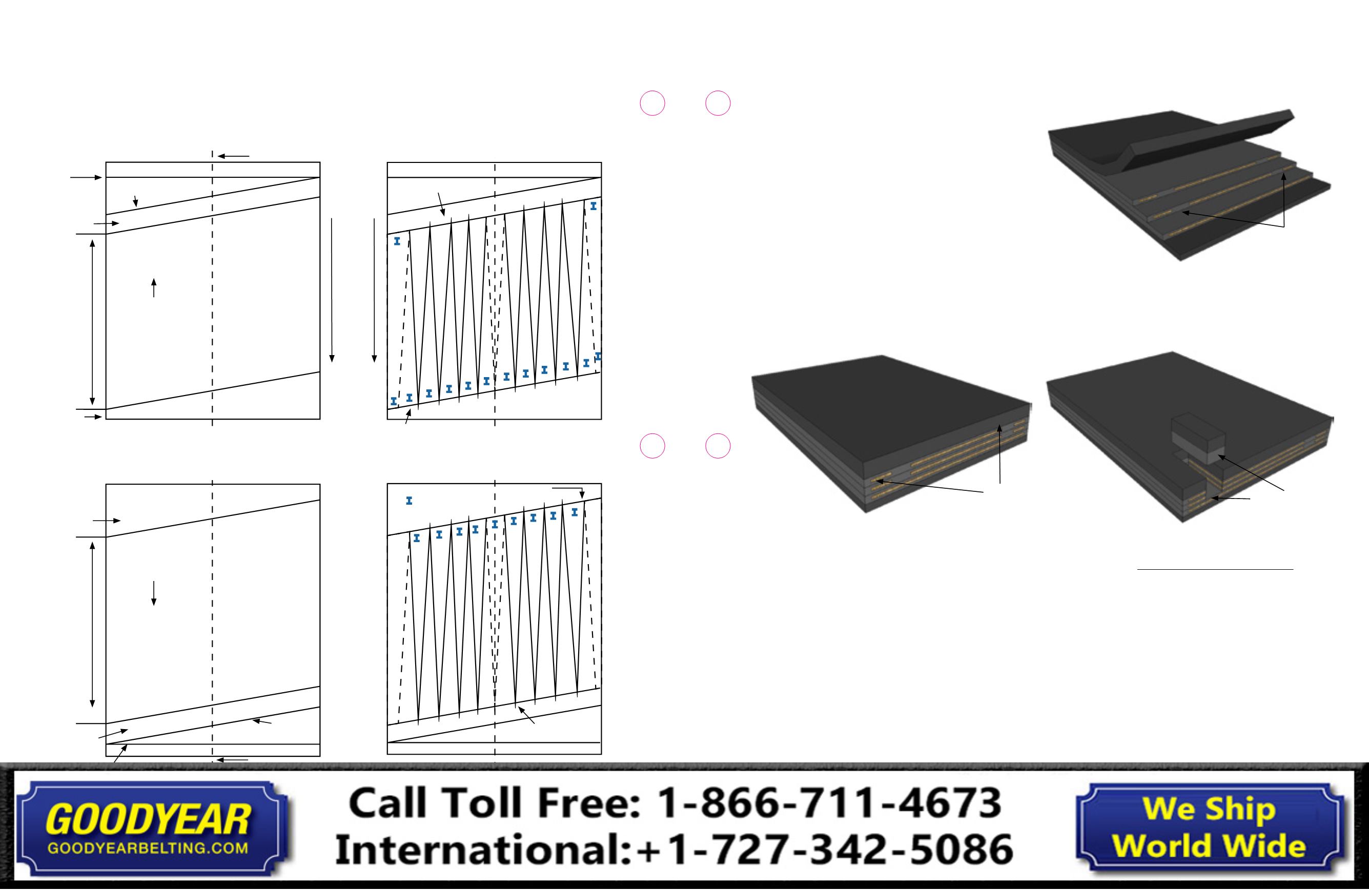
Bend zones
Bend zones stepped down
with adjacent plies.
Bend zones stepped down
with adjacent plies.
ContiPipe™ Belt Splicing
QUALITY NOTICE: The splicing method to be used will be specified
by Continental ContiTech Development: Bias Step Splice or The Long
Life Full Carcass Finger Splice. Splice schematics are available for all
splices and splicing methods.
1.
Pipe Belt Splices may be made using the Bias Step
Splice method and/or the Long Life Full Carcass
Finger Splice method.
2.
The belt manufacturer will recommend the preferred
splicing method.
3.
The belt’s construction may also be a deciding factor as to
which splicing method is best.
4.
Fig. 8-1 shows the construction of a fabric pipe belt. The
areas of most concern are the bend zones at each edge
of the belt. Maintaining the bend zones when stripping
the belt ends using the Bias Step Splice method may be
very difficult.
Fig. 8-1
5.
In cases where the bend zones cannot be stripped down,
the Long Life Full Carcass Finger Splice method will be used.
6.
The Bias Step Splice is seen in Fig. 8-2. Notice how the
bend zones are even stepped down with the adjacent
ply. The bend zones for most Pipe Belts will have a fabric
modification. The modification may allow the inside
rubber to penetrate through the fabric which will make
it impossible to accurately pull/separate the plies.
Fig. 8-2
7.
Although not necessarily recommended, the bend zones
may be removed and replaced with inside rubber and a
breaker over top, then cover rubber. Refer to Fig. 8-3.
Fig. 8-3
8.
When using the Long Life Full Carcass Finger Splice
method, the bend zones will become vital parts of the
fingers and will remain as built/designed in the original
belt design.
9.
As always, the overall gauge and stiffness of the splice
are very important. The cumulative overall gauge of the
materials required to make the Long Life Full Carcass
Finger Splice must be considered/evaluated. Great care
must be taken to match overall gauge of the splice with the
overall gauge of the belt being spliced as much as possible.
#3 Draw the carcass fingers on the trailing belt end
#3 Draw the carcass fingers on the leading belt end
D
O
T
3" or 5" transition
Outside fingers are removed and center finger stays
2 in. finger base
= Fingers to
be removed
= Fingers to
be removed
2 in. finger
base
Outside fingers pointing opposite the direction of belt travel.
Outside fingers stay and center finger is removed.
3 in. or 5 in. transition
Fig. 7-9: Drawing the Long Life Full Carcass Finger Splice Pattern and the Carcass Fingers
Master line
End of belt
D
O
T
Carcass
finger
length
#1 Draw the splice dimensions on the trailing belt end
#2 Draw the splice dimensions on the leading belt end
Center line
Bias line
Transition from
belt to carcass
fingers
Belt direction
End of belt
Belt direction
Transition from
belt to carcass
fingers
Master line
Center line
Bias line
Carcass
finger
length
34
33
Conveyor Belt
Fabric Splice Manual
Conveyor Belt
Fabric Splice Manual