


 32-33 / 52

49. Install master edge guides and needed fill steel. The
master guide and fill steel should be made of aluminum
or steel. The master edge guides should be approximately
.031 in. to .063 in. (.787mm to 1.6mm) less gauge than the
belt (not the splice gauge). The edge guides must be fitted
against the belt/splice edges. The master guides and fill
steel should extend past the platen ends approximately
6 in. to 12 in. (152mm to 305mm). Balance guides should
be used to cover the remaining platen surface.
50. Install the top platen.
51.
Secure the master edge guides in place next to the splice/
belt’s edges with come-a-longs.
52. Follow the required curing specifications for the belt type
being spliced.
53. Cure time begins when all thermocouples achieve the
specified curing temperature.
54. Monitor and document the cure temperature and pressure
in two- or five-minute intervals for the duration of the cure.
55. Cool the press platens to 130°F (54°C) or lower before
releasing pressure.
56. Remove top platen, thermocouple wire and release paper.
57.
Remove edge guides.
58. Straight edge and trim all overflow from the edges
of the cure splice.
59. Buff flow from the cover skive joints. Create a smooth
transition from the belt to the splice.
Cure Specifications:
›
Cure temp: 290°F to 5°F (143°C to -15°C).
›
Cure pressure: 100 psi to 130 psi (.69 MPa to .89 MPa)
›
Cure time: Cure time will vary with belt gauge and/or belt
type. Refer to Continental ContiTech Splice Manual and/or the
specified splice schematic details for accurate cure times and
temperatures.
›
Use steel or aluminum edge guides approximately 1/16”
(1.6mm) less gauge than the belt
NOTICE: For detailed splice drawing and finger layout refer to Fig. 7-9
on next page.
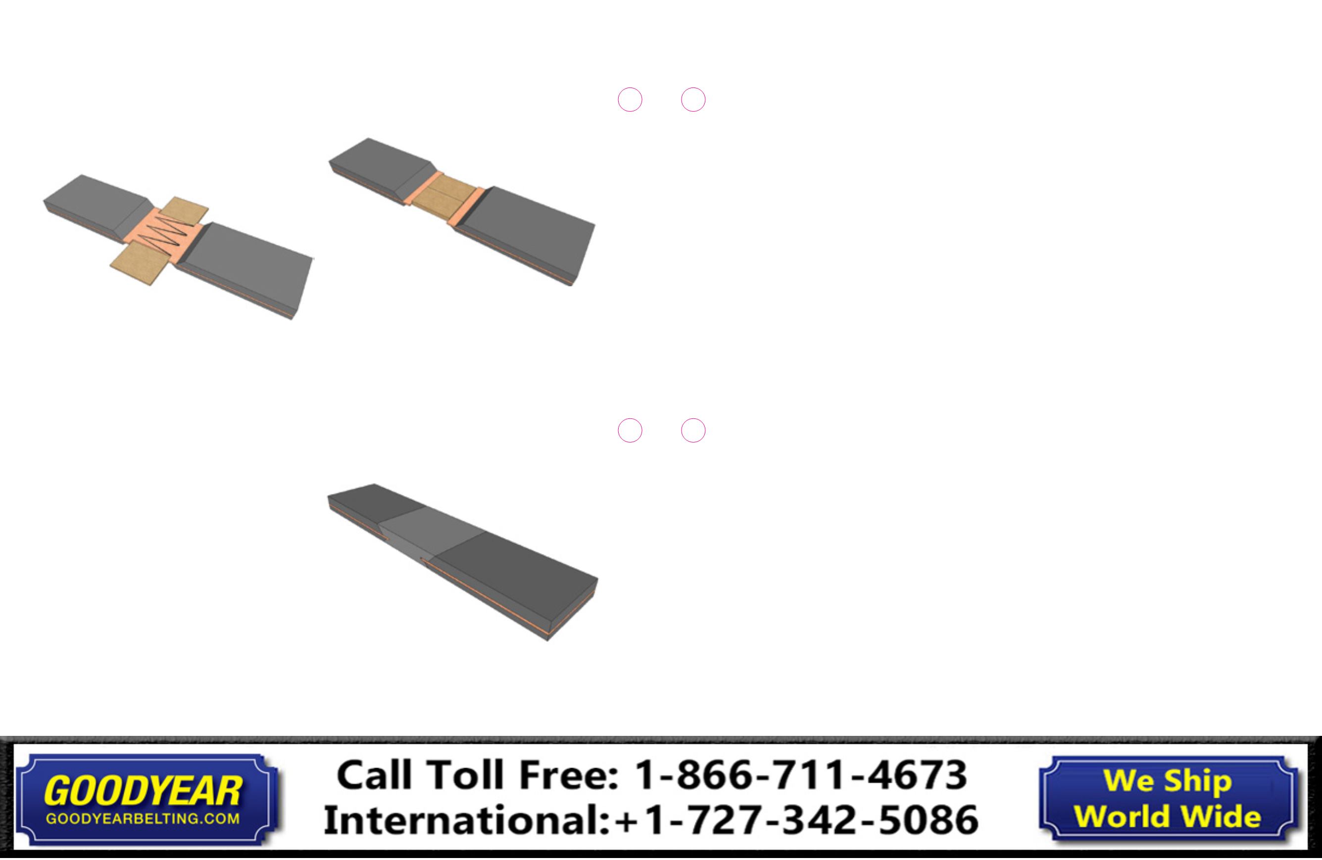
27.
Carefully dry fit the belt ends to ensure the fingers are still
properly fitted and the bottom cover composite is fitted
to each end bottom cover skives. The fingers must have
a small gap between them. Do not permit the fingers to
overlap. Refer to Fig. 7-6.
Fig. 7-6
28. Carefully lift the lead belt end. Roll it back out of the way
for now.
29. Using a flat roller, roll the fingers of the cemented trailing
belt end onto the breaker and bottom cover composite.
Using a lint-free cloth wipe the top surface of the trailing
end fingers and the exposed bottom cover composite
with the specified solvent. Allow the solvent to dry.
30. Coat the fingers and exposed carcass of the lead end
with an even layer of the specified cement. Allow the
cement to dry until tacky.
31. Install a sheet of the inside rubber over the fitted fingers
of the trailing belt end.
32. Using a narrow 1/4 in. (6mm) porcupine roller, roll the
sheet of inside rubber onto the top side of the fingers
from the trailing belt end. Roll between each finger.
33. Using a larger porcupine roller, roll the inside rubber
sheet onto the top side of the fingers. Be sure to roll flat
all gaps and voids between the fingers.
34. Position the lead end of the splice and fingers in place.
Again be certain the fingers do not overlap.
35. Roll/press the fingers in place.
36. Using a clean, lint-free cloth, wipe the top side of the
installed fingers with the specified solvent. Allow to dry.
37.
Place a sheet of the specified inside rubber over the fitted
fingers and roll in place using the narrow porcupine roller
between the fingers and the wide porcupine roller on the
top side of the fingers.
38. Install noodles around each finger to fill all voids/low
areas in the splice.
39. Using a clean, lint-free cloth, wipe the top side of the fitted
carcass splice with the specified solvent. Allow to dry.
40. Tightly wrap the breaker. Working from the outside edges,
roll the breaker in place. Refer to Fig. 7-7.
Fig. 7-7
41.
Fit the breaker together over one of the center fingers.
Do not overlap the breaker. Leave a small gap/seam
approximately 1/32 in. (.787mm) wide. Be sure the breaker
is tightly wrapped around the edges and fitted/rolled
securely in place.
42. Place noodles over each seam of the breaker.
43. Roll with a porcupine roller.
44. Using a clean, lint-free cloth and the specified solvent,
wipe the breaker and the bottom surface of the top cover
rubber. Allow to dry.
45. Install the top cover rubber and the edge rubber. Be sure
to have a tight fit at the 45° cover skives. Refer to Fig 7-8.
Fig. 7 -8
46. Build up the edges of the splice to match
the plane/line of the belt’s edges.
47.
Cover the splice area with release paper.
48. Install required thermocouple wires on the release paper
covering the top cover rubber.
32
31
Conveyor Belt
Fabric Splice Manual
Conveyor Belt
Fabric Splice Manual