


 28-29 / 52

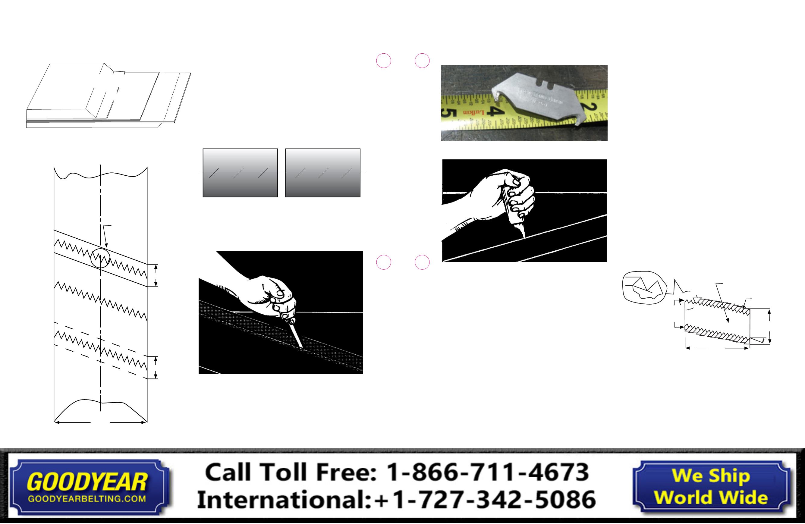
Fig. 6-5
Fig. 6-6
20. Prod under the edge of the fingers to be removed
from each ply.
21. Repeat steps 4-12 for opposite end.
22. Care must be taken to assure that “trailing” fingers are
opposite of the direction of travel or the outside fingers are
pointing opposite the direction of belt travel.
23. When both ends are completed, “dry fit” together to assure
proper alignment. These ends should be “center-lined” to
assure straight. Check to make sure that none of the fingers
are touching. Trim all fingers that are touching. There should be
3/16 in. to 1/4 in. (48mm - 64mm) gap between ALL fingers.
24. Mark the positions of the cover skives on the release paper
covering the bottom platen of the press. This will allow
cutting of the fill-in strip for the bottom later.
25. Verify the belt end alignment and secure belt ends in place.
26. Brush a coat/layer of the specified cement to each belt end.
Be sure to cover the inside edges of the fingers with cement.
27.
Allow the cement to dry until tacky.
28. Build the bottom cover insert with the following: bottom
cover rubber, breaker, (inside gum between fingers on
breaker), and inside gum, against the carcass.
NOTE: The fingers cut in the breaker fabric should be approximately
1/2” (12mm) from the bottom of the cover skives.
29. Lay bottom insert (assembled with breaker and inside
gum) on platen. Align with skive marks made earlier on
the press surface. Cut skives to match belt, coat with the
specified cement and fit one end to the assembly.
30. Lay belt end down flat and align fingers. Be sure that
fingers are straight.
31. Apply inside rubber to the 2
nd
and 3
rd
steps only, including
fingers, stitch down around fingers, and use razor knife to
trim and remove inside gum from area on top of fingers
(on top ply).
32. Place this inside gum on the top of the fingers on the
bottom ply.
33. On the end of the belt folded over, apply noodles around
edge of fingers (opposite of side that the inside gum was
applied to).
34. Lay down folded over end, checking alignment of the
fingers.
35. Build the TOP cover insert with the following: top cover,
breaker (inside gum between fingers on breaker), and
inside gum, against the carcass.
NOTE: Fingers on the breaker should be at least 1/4 in. (6mm) from the
bottom of the cover skives at each belt end.
36. Fig. 6-7 shows the breaker with 2 in. fingers
Fig. 6-7: Breaker: detail geometry
37.
Using a clean, lint-free cloth wipe the 45° cover skives
with the specified solvent. Install the top cover insert.
The specified cement may be used if additional green
tack is needed.
38. Properly set up the vulcanizer, cure the splice in accordance
with Continental ContiTech Cure Specifications.
39. A minimum of one thermocouple per heating element
shall be used, with the time, temperature and pressure
recorded at determined intervals.
40. This splice shall be water cooled to at least 130°F (54°C)
before releasing the cure pressure.
Fig: 6-2
Fingers added at the end of each step of the Straight
Bias Splice to make the Bias Finger Splice.
Straight Bias Splice then make fingers at the end of each ply.
Top Cover
45° Cover Skive
Trailing End
Ply
#1
Ply #2
Ply
#3
Part A
See Diagram 4
For Details
Part B
Width
21 in. (533mm)
11. Fig. 6-2 illustrates the fingers at the end of each step.
12. Flip belt and remove rubber from (bottom) insert first.
NOTE: Remove the rubber 1 in. (25mm) below the ply cut (this will be
the end of the fingers). Make certain that skive is on a 45° angle. Buff
the 45° cover skives with care not to damage the fabric.
13. Identify and mark the center line on each belt end. This
is a reference point for drawing the fingers and for belt
alignment once the fingers are cut (Fig. 6-3).
Fig. 6-3
14. Remove the top cover rubber from the top fill strip area.
15. Using a single ply knife carefully cut the first ply (bias line)
(Fig. 6-4).
Fig. 6-4
16. From the bias line, remove the Top Cover Rubber and first
ply full length of the splice.
17.
Remove the bottom cover insert/fill strip.
18. Mark each step length plus finger length on the bare
carcass fabric.
19. Cut and remove each step length. The 1/4 in. (6.4mm)
Stanley #11-961 “hook” type blade is specified for use
when cutting out the fingers. A 1/4” Stanley #11-961 “hook”
type blade should be used. Use care to assure they are
fully cut out (Fig. 6-5 and Fig. 6-6).
21 in. (533mm)
Detail “A”
Finger on Breaker
2 in.
2 in.
18 in.
(Including
Fingers)
Breaker Materials
Nylon/Nylon
Fill Gum
22°
21 in.
Width
28
27
Conveyor Belt
Fabric Splice Manual
Conveyor Belt
Fabric Splice Manual