


 42-43 / 52

Solar-Shield® XL 750 Splicing
Splice Dimensions
Currently Solar-Shield® XL 750 belts are being spliced using a
Bias Step Splice and are produced with three types of carcass:
Polyester, Fiberglass or Nylon.
Please read the following instructions for detailed specifications
matching the type of Solar-Shield® XL 750 carcass to be spliced.
1.
Cure temperature and pressure remain constant at 325°F/
136°C and 100 to 130 psi (.689 to .89 MPa) for each
carcass type.
2.
Step lengths will vary depending on the carcass type.
3.
Do not shorten the specified step lengths.
4.
Cure the splice to the specified time, temperature
and pressure.
5.
Follow the established best practices for splicing
Continental ContiTech Solar-Shield® belting.
6.
Use the Continental ContiTech specified splice materials for
Solar-Shield® XL 750 belt splices.
7.
Be certain the splice materials have not exceeded the
established shelf life.
8.
Charts containing the step lengths, carcass type and
carcass gauges are available in the Solar-Shield® XL 750
Section of the current “Heavyweight Conveyor Belt Guide”
edition and in table A-1 and A-2 of this document.
Splice Bias
The bias lengths should be such that the entire cover insert
gum strip can be cured in a single setting of the vulcanizer. The
recommended bias lengths are suitable for the most commonly
used vulcanizers but they can be adjusted up to
2 in. or 3 in. (50mm - 75mm) if necessary.
NOTE: Bias can be made to match the bias on the vulcanizer. The
most common are 20° and 22°. To get the bias for 20° - multiply the
width of the belt x 0.36. To find a 22° bias, multiply the width x 0.40.
It is recommended that the entire splice be cured in a single
cook/vulcanizer setting.
Step Length/Curing Chart
The last step should be increased by a minimum of 1 in. (25mm) or 2 in. (50mm) when laying out a splice to allow for trim.
Table A-1
Vulcanized Rating (PIW)
250
220
375
330
400
500
600
800
1000 1200
Imperial
Number of plies
2
2
3
3
2
4
3
4
5
6
Fabric Type
P/N
Glass
P/N
Glass
P/P
P/N
P/P
P/P
P/P
P/P
Carcass Gauge (in.)
0.108 0.152 0.182 0.239 0.178 0.253 0.251 0.340 0.429 0.518
Step Length (in.)
12
18
12
18
16
12
16
16
16
16
Metric
Number of plies
2
2
3
3
2
4
3
4
5
6
Fabric Type
P/N
Glass
P/N
Glass
P/P
P/N
P/P
P/P
P/P
P/P
Carcass Gauge (mm)
2.7
3.8
4.6
5.9
4.5
6.4
6.4
8.6
10.9
13.2
Step Length (mm)
300
460
300
460
410
300
410
410
410
410
Lap Splice (Fig. 10-2)
1.
In this type of splice only the bucket
bolts join the belt.
2.
The ends of the belt are simply
overlapped a minimum of four
buckets and fastened with the top
row of bucket bolts passing through
both pieces of belt.
3.
This method should not be used for
belts over 5/8 in. (15mm) thick since
bumping and excess stress will result
when bending over the pulleys.
4.
The belt should be fastened so that
the pulley side end is always trailing
when going over the pulleys.
Mechanical or Plate Fastener Splice
This method is only suitable for lightly tensioned applications.
Plylon® Plus belts may be installed with this type of splice at their
full elevator tension rating. Ratings of other fabrics require
a 50% reduction.
Fasteners should be chosen in accordance with the fastener
manufacturer’s recommendations.
Oil Well Splice (Fig. 10-3)
1.
This type of splice is sometimes used on light duty
applications where the belt gauge is thin and the tensions
are low. Some users have successfully developed Oil Well
splices that are tailored to their equipment and type of belt.
For others, the following guidelines should be adhered to:
2.
Not to be used on any elevators running at more than 50%
of rated belt tension.
3.
Clamps should extend to within 1/2 in. (12mm) of belt
edges. If they are too much shorter than the belt width, the
belt may tend to crease around clamp ends and tear.
4.
Plates used to make the clamps should be heavy enough
to spread the clamp pressure over as much belt area as
possible. Thickness of 1/4 in. (6mm) for light belts and
service to 1/2 in. (12mm) for heavy belts and service are
generally acceptable.
5.
Bend as large a radius as is possible. Radii over 1 in. (25mm)
are probably rarely used but even a 1 in. (25mm) radius
can induce enormous ply bending stresses in the belt.
6.
Form the clamps by bending steel plate rather than
rounding one edge of a steel angle bar.
7.
Keep bolt holes as far from the ends of the clamps as
possible; twice the thickness of the belt with a 1 in.
minimum. Less than this is no doubt frequently used
with success, especially in light service, but it could
lead to reduced splice life.
8.
Install clamps tightly then retighten at frequent intervals. In this
regard, the more the rubber in the belt construction, the greater
the possibility of some compression set early in the splice
life, which could cause the clamp to loosen. This is the same
procedure as is commonly recommended with mechanical
conveyor belt fasteners.
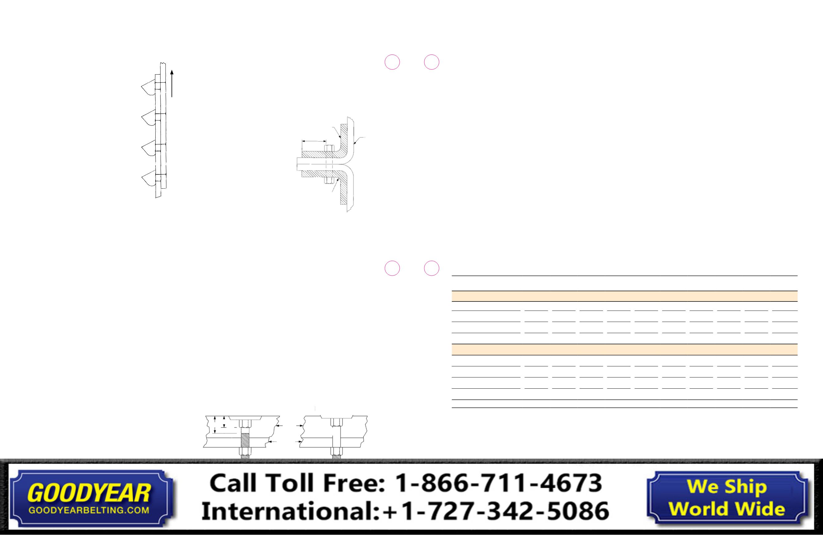
Attaching Buckets
1.
On thin gauge belts, it is
worthwhile to note that the
bucket bolt heads properly
seat themselves in the pulley
cover the belt (Fig. 10-4).
2.
The unthreaded bolt neck
should not bottom out on the
bucket before seating itself
properly in the belt. If this
happens, the bolts will likely
tip and cut their way through.
A different style bolt should
be utilized in this case.
3.
Plylon® Plus elevator belting may be thinner than
conventional belting that has been used on a specific
installation and, therefore, requires particular
consideration of the proper bucket bolts to be used.
Note the drawing of the bolt shown in Figure 10-4.
In any specific case the bolt used should have an “A”
dimension of at least 1/16 in. (1.5mm) shorter than
the overall Plylon® Plus belt gauge. In addition, the “B”
dimension should be at least 1/16 in. (1.5 mm) less than
the overall thickness of belt, bucket wall and any washers
used. The nuts should be run down far enough to get good
set and compression on the bolt head.
4.
In heat applications, an asbestos gasket may be inserted
between the bucket and belt contact area, and asbestos
washers on the bolt heads to reduce the heat conduction
into the belt.
5.
All bolts and fasteners should be retightened at least once
in 24 hours after start-up to allow for compression set
which normally occurs in rubber under pressure.
6.
A periodic inspection should then be undertaken and
retightening accomplished as necessary.
Fig. 10-4
Belt
1 in. min. radius
Min. twice belt
thickness
Clamp
Improper
Belt
Bucket
A
B
Proper
Fig. 10-3 Oil well splice
Belt travel
Fig. 10-2
42
41
Conveyor Belt
Fabric Splice Manual
Conveyor Belt
Fabric Splice Manual