


 30-31 / 52

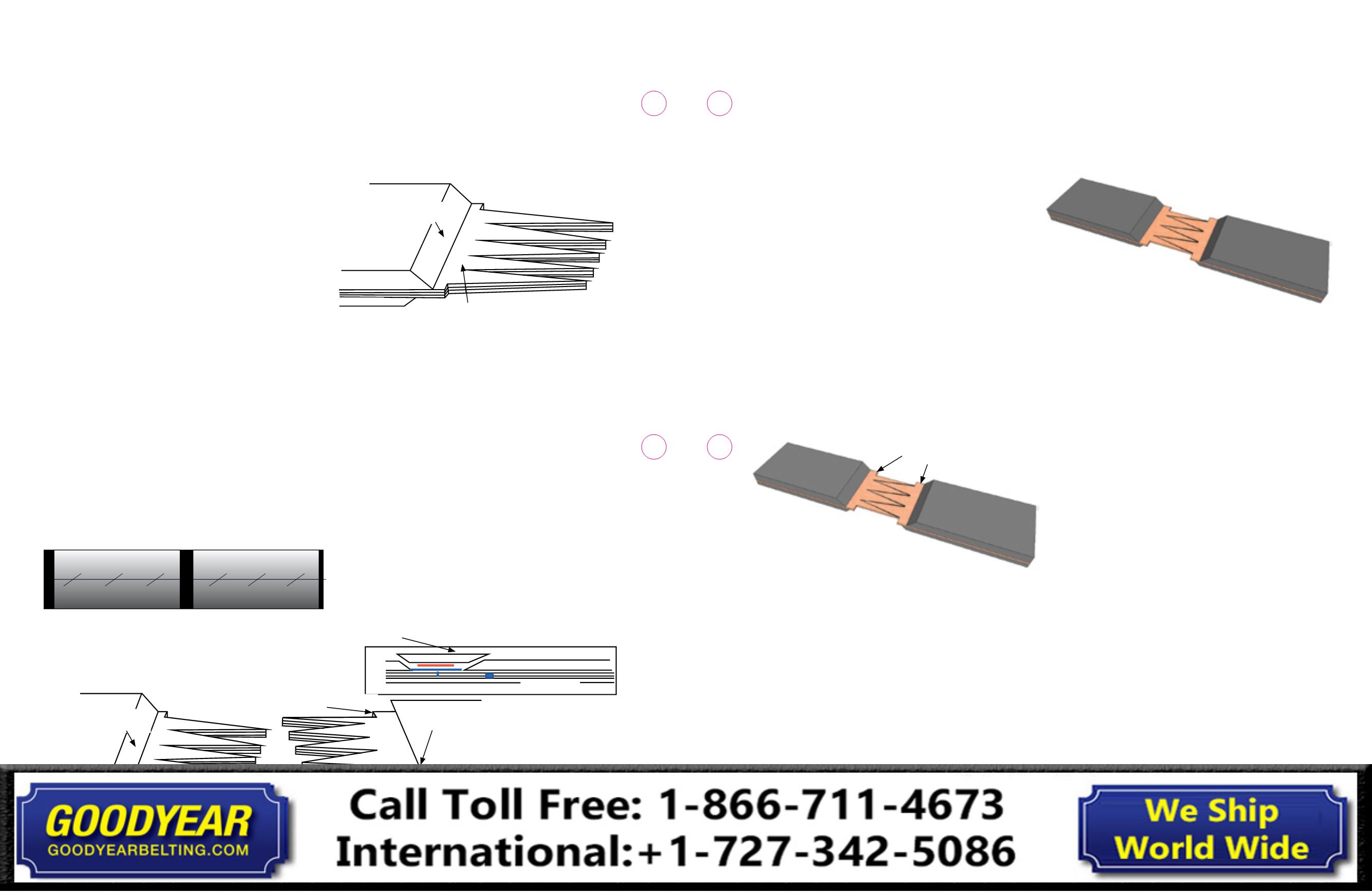
1/2 in. (12.7 mm) notch cut-off
each side of the exposed
carcass
10. Use the following instructions if a belt skiver is used: The
belt skiver will leave a thin layer of inside rubber on the
carcass allowing rubber to rubber bonding.
a. Do not remove the covers as explained in line items
6 through 9.
b. Draw out the splice and finger dimensions on
each belt end.
c. Using the skiving tool, mark and remove strips of the
top and bottom cover rubber (same width as the blade
on the skiving tool) up to the 45° cover skives. Do not
damage the adjacent ply.
d. Using a belt saw, cut out the carcass fingers.
e. Skive the top and bottom rubber from the fingers and
transition area. Do not damage the adjacent ply.
f. Continue building the splice as detailed in this document.
g. Use the specified solvent when laminating all
rubber to rubber surfaces. Cement may be used
if additional green tack is needed.
11.
Beginning approximately 1
f
in. (38mm) from the
top cover skive, notch the bare fabric and cut-off
approximately 1/2 in. to 3/4 in. (12.7mm to 19mm) along
each edge of the remaining splice length. Refer to Fig. 7-4.
Fig. 7-4
12. Transfer the center line down the center of the
bare carcass.
13. At both edges of the carcass, mark the transition distance
from the cover skive into the direction of the splice. The
transition distance is typically 3 in. or 5 in. (76mm or 127mm)
long. Refer to Fig. 7-3.
14. Draw out the fingers on the carcass, starting at the center
working towards each edge. Outside fingers must point
opposite the belt’s direction of travel. Refer to marking and
cutting out the Full Carcass Fingers. Refer to Fig. 7-9 at the
end of this section.
15. Cut out fingers: Fingers with 2 in. (50mm) base at the belt
end of the carcass will be removed. Refer to Fig. 7-9 at the
end of this section.
16. Dry fit the belt ends. Proper fit includes a gap
approximately 1/8 in. to 1/4 in. (3mm to 6mm) wide
between each finger and belt ends are aligned.
Refer to Fig. 7-5.
Fig. 7-5
17.
Pull back one end of the splice the specified distance
to create a slight gap between the fingers.
18. The splice should be centered on the press platen.
The bottom platen shall be approximately 8 in. (203mm)
longer and 8 in. (203mm) wider than the splice.
19. Secure each belt end in place.
20. Install thermocouple wires on the bottom platen.
21. Cover the bottom platen of the press with release paper
22. Mark out the splice cuts/dimensions on the release paper.
23. Brush an even coat of cement on the top and bottom of
the bare fabric and fingers on the trailing end of the splice
and the bottom only of the leading end of the splice. Be
sure to coat the inside of each finger. Allow the cement to
dry until tacky before continuing.
24. Build and position the bottom cover composite: Wipe all
cover surfaces with a clean, lint-free cloth and the specified
solvent.
a. Cut and position the bottom cover rubber to fit based
the markings placed on the release paper covering the
bottom platen. Be sure the 45° cover skives are cut to
match the cover skives at each belt end.
b. Position the breaker over the bottom cover rubber. Be
sure to have enough of the breaker extending past the
edges to overlap the entire splice. Cover the extended
breaker so to keep debris and contaminants off.
c. Using a porcupine roller, roll the breaker onto the
bottom cover rubber so to remove all possible
trapped air.
d. Using a clean, lint-free cloth, wipe the top side of the
installed breaker with the specified solvent. Allow to dry.
25. Install a sheet of the inside rubber onto the freshly
cleaned breaker.
26. Using a porcupine roller, roll the sheet of inside rubber
onto the top side of the breaker so to remove all possible
trapped air.
Long Life Full Carcass Finger Splice
NOTE: The following guidelines do not include Lockout/Tag out,
positioning belt ends, clamping belt ends or positioning the bottom
platen of the vulcanizer. A minimum cover gauge of 3/32” is required
for a long life full carcass finger splice (1/8” minimum is preferred)
1.
Determine the intended direction of the belt’s direction
of travel (DOT). The DOT will determine the layout of the
splice so the outside fingers point opposite the belt’s
direction of travel. Refer to Fig. 7-3 below.
2.
Center-line both belt ends and secure in place.
Center-lining the belt ends is necessary to ensure a
properly aligned splice.
a. Place the belt ends on the bottom platens so that
the distance between the top of the 45° cover skives
equals the splice length. The center of the splice should
be positioned on the center of the bottom platen
(both length and width). The press platens must be a
minimum of 4 to 6 inches longer and wider than the
completed splice.
b. On each belt end, mark four evenly spaced center
locations from the 45° cover skives to the end of the
work table (in the belt direction).
c. Extend a taut string from the mark at the outside ends of
each work table, supported by a suitable block to keep
the string free from interference by the belt surface.
d. Use a square to align these end marks on the belt to
the string. Check the remaining center marks and
adjust the belt as necessary until all marks are aligned.
If necessary, adjust the belt ends to complete alignment.
Refer to Fig. 7-1
Fig 7-1
3.
Outline the splice dimensions on both belt ends.
4.
Offset the top and bottom cover skives by approximately
1/2 in. Refer to Fig 7-2. Install the Reverse Cover Skive on
the leading end 45° cover skive as shown in Fig. 7-3.
Fig. 7-2
5.
Carefully cut the top and bottom 45° cover skives.
Do not cut, nick or damage the fabric.
6.
Prod and lift the corner of the covers along the
45° cover skive.
7.
It is recommended to remove the pulley covers first if it
is a much thinner gauge than the top cover. It may be
necessary to remove the covers in strips.
8.
Remove the top cover. It may be necessary to remove
the covers in strips.
9.
Carefully buff the cover skives and approximately one
inch of the adjoining cover.
Splice
Belt End
Belt End
45° Skive
Trailing End
Top Cover
Pulley Cover
3 in. Transition Each End
45° Skive
Trailing End
Top Cover
Pulley Cover
3 in. Transition Each End
Directional Cover Skive
1/2 in. x Full Length Notch
45° Reverse Cover Skive
Lead End
3 Ply Carcass
Direction of Belt Travel
Outside Finger
Offset Cover Skives approximately 3/8"
The breaker must be wrapped tightly around the finger splice
Fig 7-3
30
29
Conveyor Belt
Fabric Splice Manual
Conveyor Belt
Fabric Splice Manual