


 24-25 / 52

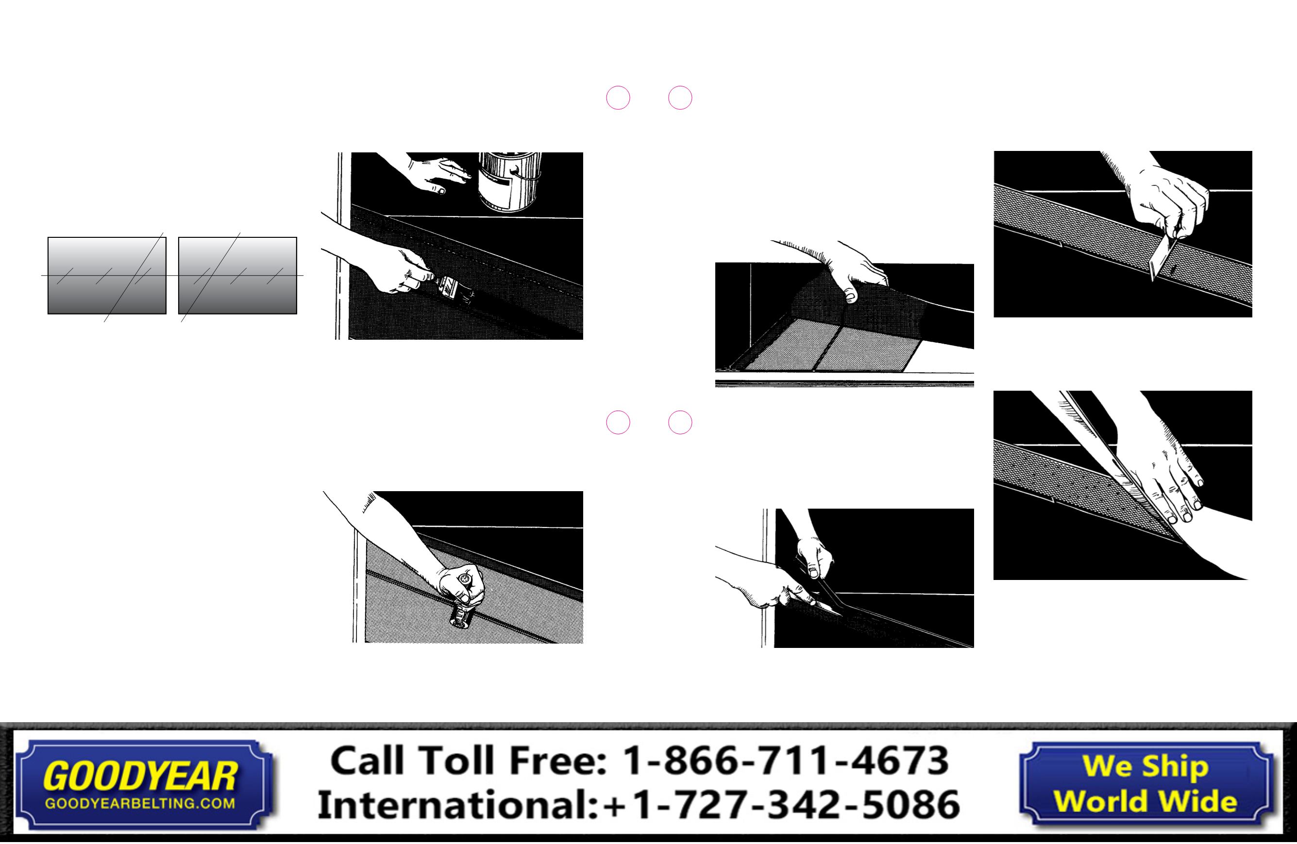
26. About 2 in. - 3 in. (50mm-75mm) from the cut just made,
make a cut through the film only. Remove the 2 in. - 3 in.
(50mm - 75mm) strip of film.
27.
Assemble breaker, fill-in gum, and release material on the
bottom side using the same system except the bottom
gum is to overlap the original cover 1/16 in. to 3/32 in.
(1mm to 2mm).
28. With the belt edges properly aligned, carefully lay the ends
together making a tight uniform joint at the bottom ply.
Make sure fabric is not overlapped (Fig. 5-16).
Fig. 5-16
29. Remove the remaining film and lower the remainder of the
splice into place. Keep edges aligned.
30. Trim the top ply step/joint – Leave a gap of approximately
1/32 in. to 1/16 in. (1mm to 2mm) wide at the ply seam/
joint. All ply seams must have a gap of 1/32 in. to 1/16 in.
(1mm to 2mm). Place a noodle or narrow strip of inside
rubber over each ply seam gap (Fig. 5-17).
Fig. 5-17
31. Apply an even layer/coat of the specified cement
to the fill-in area on the topside. Lay in the breaker –
The breaker must be centered over the ply seam and
approximately 1/4 in. (6mm) from the bottom of the 45°
cover skives. The breaker is approximately 1/2 in. (12mm)
narrower than the bottom of the fill strip area.
32. Using a clean, lint-free cloth and the specified solvent,
clean one side of the top fill cover rubber. Roll it into
place and trim.
33. Use a small straight edge to check for the proper gauge of
fill-in gum. The straight edge should make imprints on the
gum (Fig. 5-18). Any low spots should be built up.
Fig. 5-18
34. Prick the fill-in gum with an awl to release trapped air.
Cover with a cemented strip of release material 2 in.
(50mm) wider than the gum strip (Fig. 5-19).
Fig. 5-19
20. Refer to Fig. 5-13: Mark a center line on each end of the
belt by connecting three center marks, the farthest being
a minimum of three times the splice length distance from
the master line. Align the belt using the center marks and
dry fit the ends to ensure the steps fit together properly.
Do not allow any steps to overlap; trim to fit as necessary.
After completing adjustments, secure the belt ends in this
position. It is common to C-clamp the belt to the work
table and nail blocks of wood to the table flush with the
belt edges to prevent lateral movement.
Fig. 5-13
a. Center-lining the belt ends is necessary to ensure a
properly aligned splice.
b. Place the belt ends on the bottom platens so that the
distance between the top of the 45° cover skives equals
the splice length.
c. The center of the splice should be positioned on the
center of the bottom platen (both length and width).
d. The press platens must be a minimum of 6 in. - 8 in.
(152mm - 203mm) longer and wider than the
completed splice.
e. On each belt end mark three evenly spaced center
locations from the 45° cover skives to the end of the
work table.
f.
Extend a string from the marks at the outside ends of
each work table, supported by a suitable block to keep
the string free from interference by the belt surface.
g. Use a square to align these end marks to the string.
h. Check the remaining center marks and adjust the belt
as necessary until all marks are aligned.
i.
Verify the splice length distance between the 45°
cover skives.
j.
Secure the belt ends in this position. Typically C- clamps
are used to secure the belt to the work table.
k. Nail blocks of wood to the table flush with the belt
edges to prevent lateral movement.
21. Using a clean, lint-free cloth, clean all rubber areas
with the appropriate solvent and allow to dry completely.
22. Apply one even layer/coat of the specified cement over the
entire fabric step area starting at the first ply fabric cut
(Fig. 5-14).
Fig. 5-14
23. After the cement is dried to a tacky feel, using a clean,
lint-free cloth and specified solvent, wash/wipe one side
of a sheet of the specified inside rubber. Apply the inside
rubber to the fabric step area starting at the first ply cut/
bias line, proceed to the end of the splice area (Fig. 5-15).
Be sure the correct gauge gum and the proper number
of layers are used. Roll the rubber thoroughly with a
2 in. (50mm) roller to remove all possible trapped air.
The rubber is applied to only one of the stepped ends.
Do not remove poly/film from the gum at this time.
Fig. 5-15
24. On the end which now has the splice gum, mark a ply
cut-off line as follows. Measure both edges from the master
line. On one edge measure the total step length plus bias
length. On the other edge measure only the total step
length. Then draw the cutoff line.
25. Cut film, gum and the one ply with a smooth straight cut
across the line just marked.
Splice Areas
24
23
Conveyor Belt
Fabric Splice Manual
Conveyor Belt
Fabric Splice Manual