


 14-15 / 52

Existing Splices Loaded onto
a Conveyor System
Splices made prior to installing the belt onto the conveyor
system must be clearly marked/identified so the installation
crew can identify the direction of travel.
Establishing a Master Line
1.
The master line is normally the first mark to be made on
each of the two ends to be spliced.
2.
A true master line will ensure the splices are at a minimum
started off square. The mark is drawn straight across the
belt’s width at a distance equal to the total splice length
plus trim allowance from the belt end.
3.
Three methods of locating and squaring the master line
are as follows:
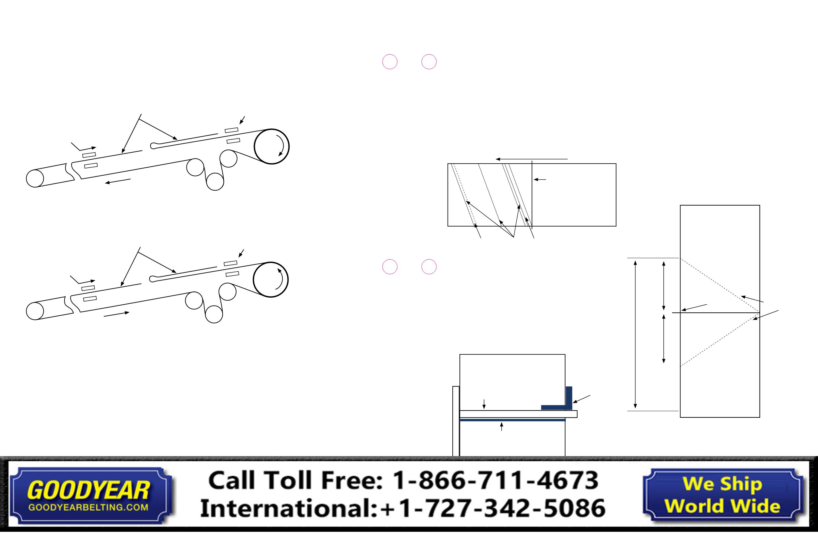
Square and Straight Edge (Fig. 3-8)
1.
Check the master line by laying the square along the
opposite edge. As a final check, mark off the bias lengths
on each edge and check that the two diagonal lengths
are equal.
2.
From the end of the belt, measure back the length of splice
plus trim allowance.
3.
Use a square and straight edge to the draw master line.
4.
To prepare the second (opposite) belt end, fold the belt
back and repeat the procedure. Make sure that the bias is
on the opposite edge on the other end.
Triangulation (Fig. 3-9)
1.
From the end of the belt, measure back along one edge
the splice length plus trim allowance. Mark the edge.
This mark is then the center point of a line exactly 4 ft.
(1200mm) long drawn along this edge.
2.
From each end of the 4 ft. (1200mm) line measure equal
diagonal lengths to the opposite edge and mark (Fig. 3-9).
Draw the master line.
3.
This method is common on belts 72 in. (1,800mm) and wider.
Fig. 3-9: Triangulation Method
Swinging Arc (Fig. 3-10)
1.
Carefully mark a point at the exact center of the belt width.
2.
Measure from this center point and make a mark at each
edge near the end. These two diagonal measurements
must be exactly equal.
3.
From each of the two-edge marks measure back the total
splice length plus trim allowance.
4.
Mark the edges and draw the master line.
Bottom Fill Step Lengths Bias Line and Top Fill
Master Line
DOT – Direction Of Travel: Bottom Fill Leads Direction Of Travel
Fig. 3-7
Fig. 3-8
Master line by straight edge and square
Straight edge
Master line
Square to
validate the
master line
is straight
1
2
3
4
5
6
7
8
1 2 3 4 5 6 7 8 9 10 11 12 13 14 15 16 17 18 19 20 21 22 23 24 25 26
Equal lengths
from the 24 in.
marks
Master line
Belt end
24 in.
Overall splice lenth
24 in. equal
distances from
this mark
Direction of Splice and Bias
1.
In most level or inclined (power-requiring) belts, it is recommended that the belt ends be
stepped down so that the pulley side joint leads and the top side joint trails the direction
of belt travel (Fig. 3.5).
Fig. 3-5: Splice Direction - Incline (Power-requiring)
2.
In most decline (regenerative) belts, the splice is prepared according to Fig. 3-6 so that the
pulley side joint trails and the top side joint leads the direction of belt travel.
Fig. 3-6 Splice Direction - Decline (Regenerative) Belts
3.
An exception to the above splice directions sometimes occurs when splicing a new belt into
an old one.
4.
If the old belt covers are badly worn, then both ends of the new section should be stepped
from the pulley side. This leaves new unworn top cover on both splices and will provide
more uniform vulcanizer pressure. In doing this, one splice will run in reverse to the usual
recommendation.
5.
Be sure that the bias direction will conform to that of the vulcanizer and that the entire cover
insert can fit within one setting of the vulcanizer.
6.
Slight adjustments of 1 in. to 3 in. (25mm to 75mm) of the bias angle are permissible if necessary.
Pull here
Direction of belt travel
Tear down from this side
Clamped off here
Splicing area
Drive
pulley
Pull here
Direction of belt travel
Tear down from this side
Clamped off here
Splicing area
Drive
pulley
Drive
pulley
24 in.
14
13
Conveyor Belt
Fabric Splice Manual
Conveyor Belt
Fabric Splice Manual