


 7 / 60

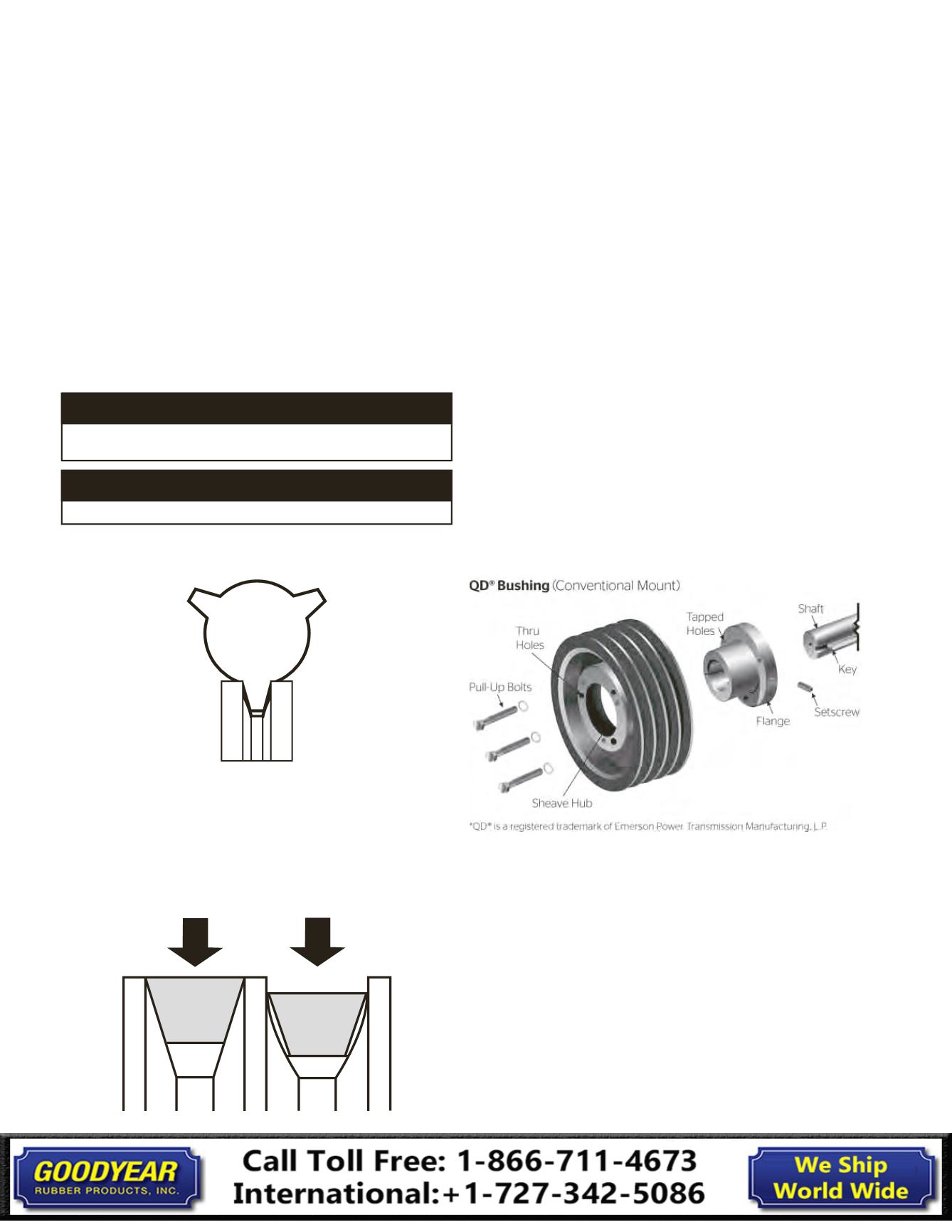
Like this
Not this
WARNING
Disconnect power supply to the machine before removing
or installing sheaves or belts.
WARNING
Do not reinstall damaged or worn sheaves on equipment.
of the belt should be flush with or slightly above the outer
diameter of the sheave. Remember that if the belt top is below
the sheave’s outer diameter, the groove is worn. Perform
further inspection if possible. Use the Groove Dimension Tables
1 and 2 (on pages 3-6) to determine if excessive wear has
occurred or to select replacement belts and sheave cross sections.
2. Install hardware
Always remember to select the correct sheave. Then, after
you make the correct selection, be sure to install the
sheaves correctly.
Before performing any installation, follow correct lockout
procedures to prevent any accidents.
IMPORTANT:
Disconnect power supply to machine
before
doing ANY work
.
QD® Bushing
If the sheaves are made with a QD® hub,
follow these installation and removal instructions:
3. How to install a sheave with a QD® hub
Insert the bushing in the hub and line up bolt holes.
Insert the pull-up bolts and turn until finger tight.
Hold the loosely–assembled unit so the bushing flange points
toward the shaft bearings. Reverse mounting the QD® bushing
can be advantageous for some applications.
Slip the unit onto the shaft and align the hub in the desired position.
V-Belts
Installation Guide
V-Belts
Installation Guide
1. Inspect sheaves
The following sections outline installation procedures that will
ensure maximum life and performance for your V-belts.
Check sheaves for cleanliness, damage and wear whether you
are replacing an existing belt, performing routine maintenance
or installing a new drive.
Use a stiff brush to remove rust and dirt. Use a soft cloth to
wipe off oil and grease. Select the proper sheave groove gauge
and template for the sheave diameter. Insert the gauge in the
groove and look for voids that indicate dishing or other uneven
and abnormal wear.
An alternative method for checking for sheave groove wear
is to place a new belt in the sheave groove. Note that the top
Standard
D
Section
PO
12.0 to 12.99
34°
PO
13.0 to 17.0
36°
PO
Over 17.0
38°
Sheave Groove Gauge
7