


 5 / 60

b g
b e
a
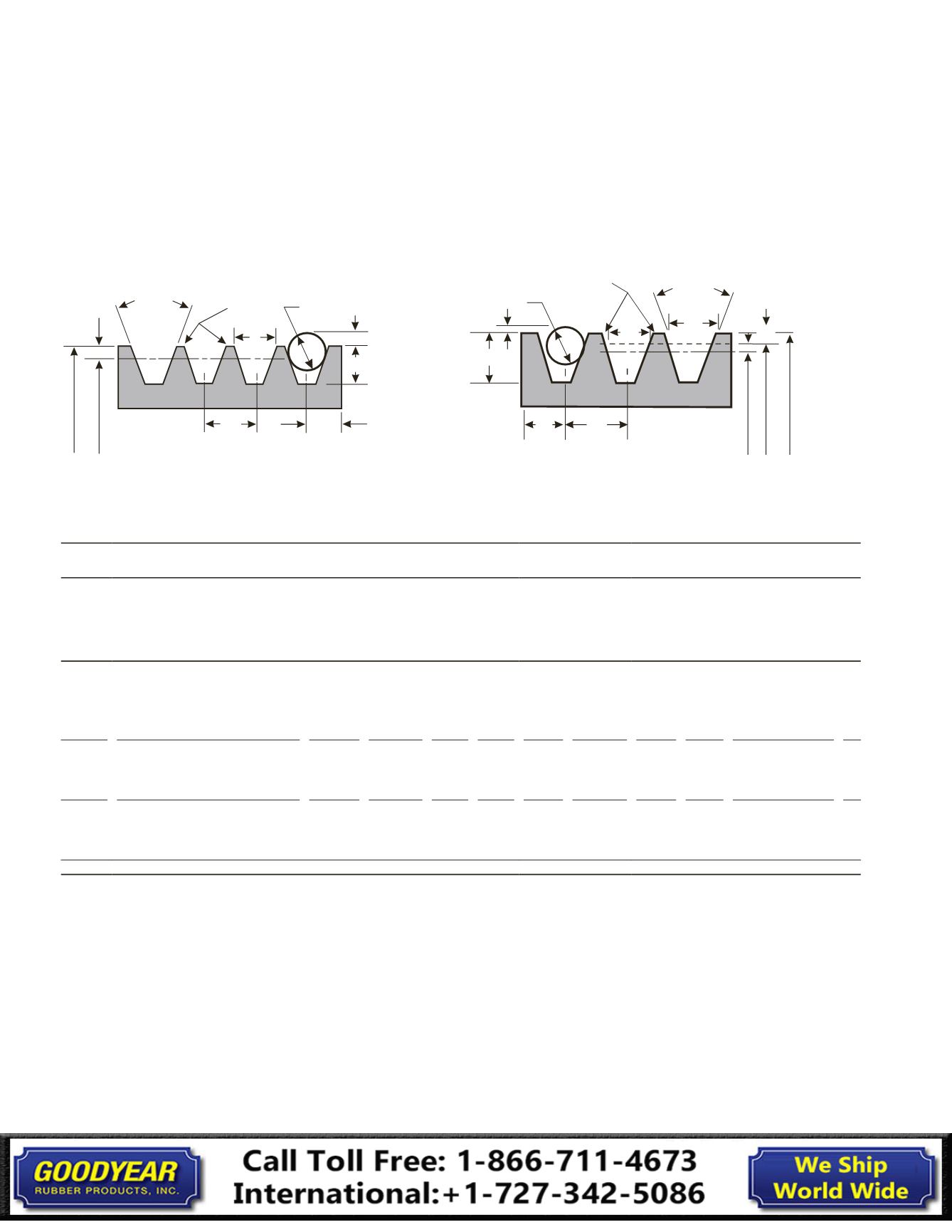
Industry Standard Groove Dimensions for HY-T® Wedge Belt Drives
Standard Groove Dimensions
Deep Groove Dimensions
h g R B
d B
S e
S g
Groove
Angle
ୋ
File Break
All Sharp
Corners
a
S e
S g
R B
h g
d B
b e
&
b g
E"ective and
Outside Diameter
Pitch
Diameter
Groove
Angle
ୋ
File Break
All Sharp
Corners
h e
Outside
Diameter
Pitch
Diameter
E"ective
Diameter
Face Width of Standard and Deep
Groove Sheaves
Face Width = Sg (Ng – 1) + 2 Se
Where: Ng = Number of Grooves
V-Belts
Installation Guide
Table 2 Groove Dimensions
Standard Groove Dimensions (in.)
Design Factors
Cross
Section
Standard Groove
Outside Diameter
Groove
Angle
±
0.25
Degrees
b
g
±
0.0005
b
e
Ref.
h
g
Min.
R
B
Min.
d
b
±
0.0005
S
g
±
0.015
S
e
Minimum
Recommended
Outside Diameter 2a
3V,
3VX
Up through 3.49
Over 3.49 to and including 6.00
Over 6.00 to and including 12.00
Over 12.00
36
38
40
42
0.350 0.350 0.340
0.181
0.183
0.186
0.188
0.3438 0.406
0.344
+0.094
-0.031
3V: 2.65
3VX: 2.20
0
5V,
5VX
Up through 9.99
Over 9.99 to and including 16.00
Over 16.00
38
40
42
0.600 0.600 0.590
0.329
0.332
0.336
0.5938 0.688
0.500
+0.125
-0.047
5V: 7.10
5VX: 4.40
0
8V
Up through 15.99
Over 15.99 to and including 22.40
Over 22.40
38
40
42
1.000 1.000 0.990
0.575
0.580
0.585
1.0000 1.125
0.750
+0.250
-0.062
8V: 12.50
0
V-Belts
Installation Guide
Summation of the deviations from “S g ” for all grooves in any one sheave shall
not exceed
±
0.031 in. The variations in pitch diameter between the grooves in
any one sheave must be within the following limits:
Up through 19.9 in. outside diameter and up through 6 grooves – 0.010 in.
(add 0.0005 in. for each additional groove).
20.0 in. and over on outside diameter and up through 10 grooves – 0.015 in.
(add 0.0005 in. for each additional groove).
This variation can easily be obtained by measuring the distance across two
measuring balls or rods placed in the grooves diametrically opposite each
other. Comparing this “diameter over balls or rods” measurement between
grooves will give the variation in pitch diameter.
Deep groove sheaves are intended for drives with belt offset such as quarter-turn
or vertical shaft drives (see Power Transmission Belt Technical Information
Bulletin IP-3-10). They may also be necessary where oscillations in the center
distance may occur. Joined belts will not operate in deep groove sheaves.
Other Sheave Tolerances
Outside Diameter
Up through 8.0 in.
Outside diameter:
±
0.020 in.
For each additional inch of outside diameter, add...
±
0.005 in.
Radial Runout*
Up through 10.0 in.
Outside diameter:
±
0.010 in.
For each additional inch of outside diameter, add...
±
0.0005 in.
Axial Runout*
Up through 5.0 in.
Outside diameter:
±
0.005 in.
For each additional inch of outside diameter, add...
±
0.001 in.
*Total Indicator Reading
5