


 3 / 60

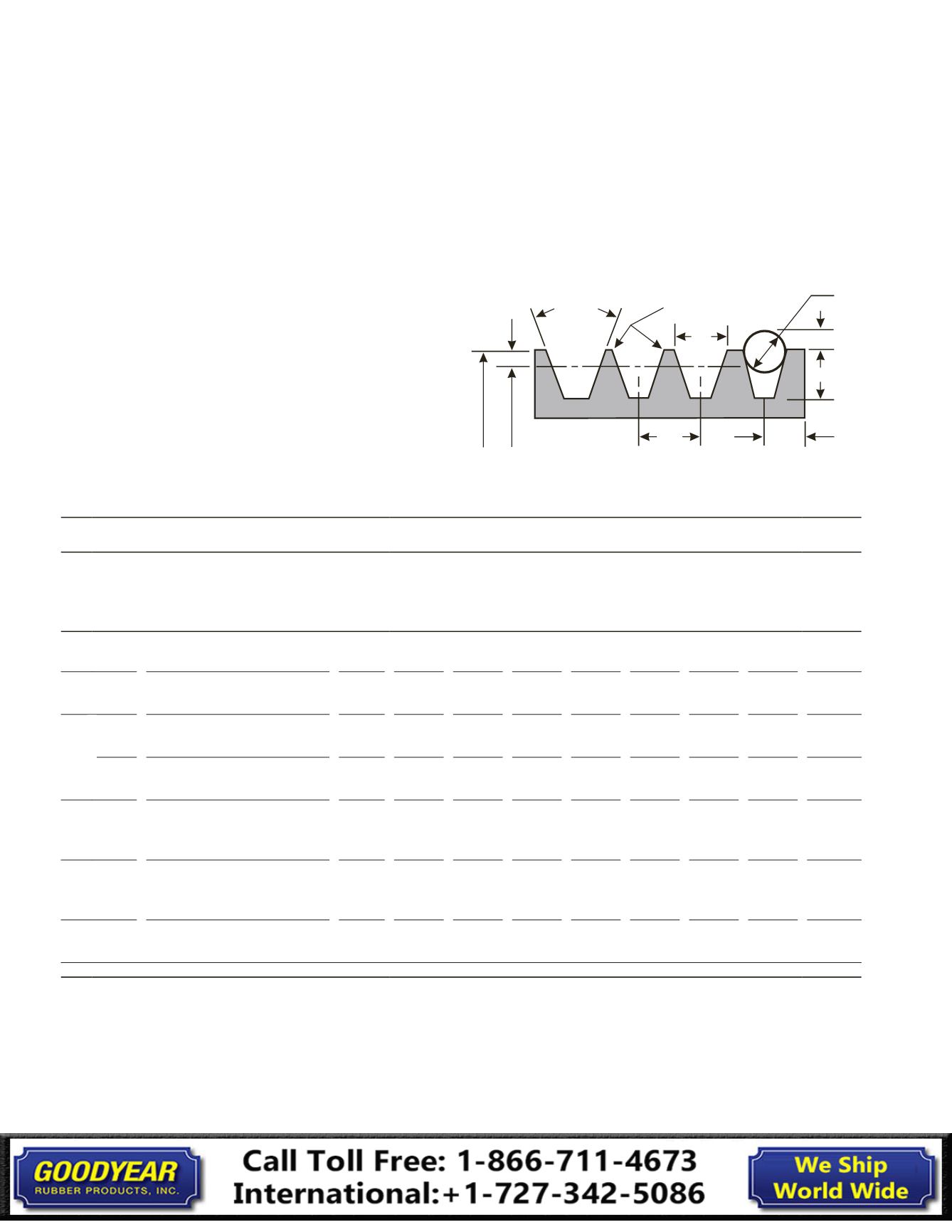
Groove
Angle
ୋ
Industry Standard Groove Dimensions for V-Belt Sheaves
File Break All
Sharp Corners
b g
d B
R B
h g
S e
S g
Standard Groove Dimensions
Outside
Diameter
Datum
Diameter
a
Face Width of Standard and Deep
Groove Sheaves
Face Width = S g (N g – 1) + 2 S e
Where: N g = Number of Grooves
V-Belts
Installation Guide
V-Belts
Installation Guide
Check sheaves for cleanliness, damage and wear each time belt
maintenance is performed and whenever belts are changed.
The inspection procedure is described on page 7 of this guide.
Use the Groove Dimensions Tables 1 and 2 (on pages 4-6) and
tolerance data below as a reference to determine if
excessive sheave wear has occurred. They can also aid in
replacement belt cross section selection, if necessary.
The tables are based on industry standard dimensions for
V-belt sheaves. Always check the original sheave specifications
if possible. Variances from industry standards can occur to
provide for special design or performance requirements.
Table 1 Groove Dimensions
Standard Groove Dimensions (in.)
Cross
Section
Outside Diameter Range
Groove
Angle
±
0.33
b
g
b
g
h
g
Min.
R
B
Min.
d
b
±
0.0005
S
g
±
0.025
S
e
S
e
A, AX
Up through 5.65
Over 5.65
34
38
0.494
0.504
±
0.005
0.460
0.151
0.152
0.4375
(7/16)
0.625 0.375
$0.090
%0.062
B, BX
Up through 7.35
Over 7.35
34
38
0.637
0.650
±
0.006
0.550
0.192
0.193
0.5625
(9/16)
0.750 0.500
+0.120
-0.065
A, AX & B, BX
Combination
A, AX
Up through 7.4
Over 7.4
34
38
0.612
0.625
±
0.006
0.612
0.233
0.229
0.5625
(9/16)
0.750 0.500
+0.120
-0.065
B, BX
Up through 7.4
Over 7.4
34
38
0.612
0.625
±
0.006
0.612
0.233
0.229
0.5625
(9/16)
0.750 0.500
+0.120
-0.065
C, CX
Up through 8.39
Over 8.39 to and including 12.40
Over 12.40
34
36
38
0.879
0.887
0.895
±
0.007
0.750
0.279
0.280
0.282
0.7812
(25/32)
1.000 0.688
+0.160
-0.070
D
Up through 13.59
Over 13.59 to and including 17.60
Over 17.60
34
36
38
1.259
1.271
1.283
±
0.008
1.020
0.416
0.417
0.418
1.1250
(1⅛)
1.438 0.875
+0.220
-0.080
E
Up through 24.80
Over 24.80
36
38
1.527
1.542
±
0.010
1.270
0.476
0.477
1.3438
(1*⅓;)
1.750 1.125
+0.280
-0.090
ୋ
Other Sheave Tolerances
Outside Diameter
Up through 8.0 in.
Outside diameter:
±
0.020 in.
For each additional inch of outside diameter add...
±
0.005 in.
Radial Runout*
Up through 10.0 in.
Outside diameter:
±
0.010 in.
For each additional inch of outside diameter add...
±
0.0005 in.
Axial Runout*
Up through 5.0 in.
Outside diameter:
±
0.005 in.
For each additional inch of outside diameter add...
±
0.001 in.
*Total Indicator Reading
3