


 78 / 84

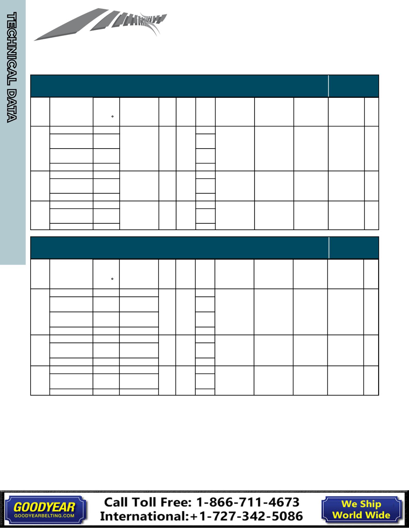
Sheave Dimension Information - According to ARPM (RMA)
Standard IP-22 (2007) (3V, 5V, 8V, 3VX, 5VX)
TABLE I-1 STANDARD GROOVE DIMENSIONS
DESIGN
(INCHES)
FACTORS
TABLE I-1 - GROOVE DIMENSIONS - INCHES
Cross
Section
Standard Groove
Effective
Diameter
Standard Groove Dimensions
Design Factors
Groove
Angle
±0.25
°
b g
±0.005
b e
Ref.
h g
Min.
R B
Min
d B
±0.0005
S g
±0.015
S e
Minimum
Recommended
Effective
Diameter
2a p
2h e
3V
3VX
Up through 3.49
36
0.350
0.350 0.340
0.181
0.3438
0.406
0.344
+0.094
-0.031
3V: 2.65
3VX: 2.20 0
Over 3.49 to and
including 6.00
38
0.184
Over 6.00 to and
including 12.00
40
0.186
Over 12.00
42
0.189
5V
5VX
Up through 9.99
38
0.600
0.600 0.590
0.330
0.5938
0.688
0.500
+0.125
-0.047
5V: 7.10
5VX: 4.40 0
Over 9.99 to and
including 16.00
40
0.333
Over 16.00
42
0.337
8V
Up through 15.99
38
1.000
1.000 0.990
0.576
1.0000
1.125
0.750
+0.250
-0.062
12.50
0
Over 15.99 to and
including 22.40
40
0.581
Over 22.40
42
0.586
Cross
Section
Standard Groove
Effective
Diameter
Deep Groove Dimensions
Design Factors
Groove
Angle
±0.25
°
b g
±0.005
b e
Ref.
h g
Min.
R B
Min
d B
±0.0005
S g
±0.015
S e
Minimum
Recommended
Effective
Diameter
2a p
2h e
3V
3VX
Up through 3.49
36
0.421
0.350 0.449
0.073
0.3438
0.500
0.375
+0.094
-0.031
3V: 2.65
3VX: 2.20 0.218
Over 3.49 to and
including 6.00
38
0.425
0.076
Over 6.00 to and
including 12.00
40
0.429
0.079
Over 12.00
42
0.434
0.080
5V
5VX
Up through 9.99
38
0.710
0.600 0.750
0.172
0.5938
0.812
0.562
+0.125
-0.047
5V: 7.10
5VX: 4.40 0.320
Over 9.99 to and
including 16.00
40
0.716
0.176
Over 16.00
42
0.723
0.178
8V
Up through 15.99
38
1.180
1.000 1.252
0.317
1.0000
1.312
0.844
+0.250
-0.062
12.50
0.524
Over 15.99 to and
including 22.40
40
1.191
0.321
Over 22.40
42
1.201
0.326
Summation of the deviations “S g ” for all grooves in any one
sheave shall not exceed
±
0.031 inch.
The variations in effective diameter between the grooves in
any one sheave shall be within the following limits:
Up through 19.9 inches effective diameter and up through
6 grooves -- 0.010 inches (add 0.0005 inches for each
additional groove).
20.0 inches and over on effective diameter and up through
10 grooves -- 0.015 inches (add 0.0005 inches for each
additional groove).
This variation can easily be obtained by measuring the distance
across two measuring balls or rods placed in the grooves
diametrically opposite each other. Comparing the “diameter
over balls or rod” measurement between grooves will give the
variation in effective diameter.
Deep groove sheaves are intended for drives with belt
offset such as quarter turn or vertical shaft drives. (See RMA IP-
3-10 -
Power Transmission Belt Technical Bulletin - V-Belt
Drives With Twist and Non-Alignment Including Quarter Turn
.)
Joined belts will not operate in deep groove sheaves.
All rights reserved. The contents of this publication may not be reprinted
or otherwise reproduced in any form without the express written permission of RMA.
TABLE I-1 DEEP GROOVE DIMENSIONS
DESIGN
(INCHES)
FACTORS
TABLE I-1 - GROOVE DIMENSIONS - INCHES
Cross
Section
Standard Groove
Effective
Diameter
Standard Groove Dimensions
Design Factors
Groove
Angle
±0.25
°
b g
±0.005
b e
Ref.
h g
Min.
R B
Min
d B
±0.0005
S g
±0.015
S e
Minimum
Recommended
Effective
Diameter
2a p
2h e
3V
3VX
Up through 3.49
6
0.350
0.350 0.340
1
0.3438
0.406
0.344
+0.094
-0.031
3V: 2.65
3VX: 2.20 0
Over 3.49 to and
including 6.00
38
0.184
Over 6.00 to and
including 12.00
0
.186
Over 12.00
42
0.189
5V
5VX
Up through 9.99
38
0.600
0.600 0.590
0.330
0.5938
0.688
0.500
+0.125
-0.047
5V: 7.10
5VX: 4.40 0
Over 9.99 to and
including 16.00
40
0.333
Over 16.00
42
0.337
8V
Up throu h 15.99
38
1.000
1.000 0.990
0.576
1.0000
1.125
0.750
+0.250
-0.062
12.50
0
Over 15.99 to and
including 22.40
40
0.581
Over 22.40
42
0.586
Cross
Section
Standard Groove
Effective
Diameter
Deep Groove Dimensions
Design Factors
Groove
Angle
±0.25
°
b g
±0.005
b e
Ref.
h g
Min.
R B
Min
d B
±0.0005
S g
±0.015
S e
Minimum
Recommended
Effective
Diameter
2a p
2h e
3V
3VX
Up through 3.49
36
0.421
0.350 0.449
0.073
0.3438
0.500
0.375
+0.094
-0.031
3V: 2.65
3VX: 2.20 0.218
ver 3.49 to and
including 6.00
38
0.425
0.076
Over 6.00 to and
including 12.00
40
0.429
0.079
Over 12.00
42
0.434
0.080
5V
5VX
Up through 9.99
38
0.710
0.600 0.750
0.172
0.5938
0.812
0.562
+0.125
- 0 7
5V: 7.10
5VX: 4.40 0.320
Over 9.99 to and
including 16.00
40
0.716
0.176
Over 16.00
42
0.723
.178
8V
Up through 15.99
38
1.180
1.000 1.252
0.317
1.0000
1.312
0.844
+0.250
-0.062
12.50
0.524
Over 15.99 to and
including 22.40
40
1.191
0.321
Over 22.40
42
1.201
0.326
Summation of the deviations “S g ” for all grooves in any one
sheave shall not exceed
±
0.031 inch.
The variations in effective diameter between the grooves in
any one sheave shall be within the following limits:
Up through 19.9 inches effective diameter and up through
6 grooves -- 0.010 inches (add 0.0005 inches for each
additional groove).
20.0 inches and over on effective diameter and up through
10 grooves -- 0.015 inches (add 0.0005 inches for each
additional groove).
This variation can easily be obtained by measuring the distance
across two measuring balls or rods placed in the grooves
diametrically opposite each other. Comparing the “diameter
over balls or rod” measurement between grooves will give the
variation in effective diameter.
Deep groove sheaves are intended for drives with belt
offset such as quarter turn or vertical shaft drives. (See RMA IP-
3-10 -
Power Transmission Belt Technical Bulletin - V-Belt
Drives With Twist and Non-Alignment Including Quarter Turn
.)
Joined belts will not operate in deep groove sheaves.
All rights reserved. The contents of this publication may not be reprinted
or otherwise reproduced in any form without the express written permission of RMA.
RMA IP-22 (2007)
Part 1 (Inch-Pound Units)
Summation of the deviations from "S g " for all grooves in any on sheave shall not exceed
±0.031 inches.
The variations in effective diameter between the grooves in any one sheave shall be wit in the following limits:
Up through 19.9 inches effective diameter and up through 6 grooves: 0.010 (add 0.0005 in. for each
additional groove).
20.0 inches and over on effective diameter and up through 10 grooves: 0.015 inches and (add 0.0005 inches
for each additional groov ).
This variation ca easily b ob ained by measuring the distance across two measuring balls or rods placed in the
grooves diametrically opposite each other. Compa ing the "diameter over balls or rod" measurement between
grooves will give the variation in effective diameter.
Deep groove sheaves are intended for drives with belt offset such as quarter-turn or vertical shaft drives. (See RMA
IP-3-10 - Power Transmission Belt Technical Bulletin - V-Belt Drives With Twist and Non-Alignment Including Quarter Turn.)
Joined belts will not operate in deep groove sheaves.
TECHNICAL DATA
POWERING GLOBAL INDUSTRY
TECHNICAL DATA
76