


 74 / 84

72
TECHNICAL DATA
POWERING GLOBAL INDUSTRY
TECHNICAL DATA
TIMING BELT
Standard and timing belts should be installed to fit pulleys
snugly, neither too tight nor too loose. The belt’s positive
grip eliminates the need for high initial tension. When a belt
is installed with a snug but not overly tight fit, longer belt
life, less bearing wear and more quiet operation will result.
Overtight belts can cause early failure and should be avoided.
With high torque, a loose belt may “jump teeth” upon startup.
If such occurs, the tension should be increased gradually until
satisfactory operation is achieved.
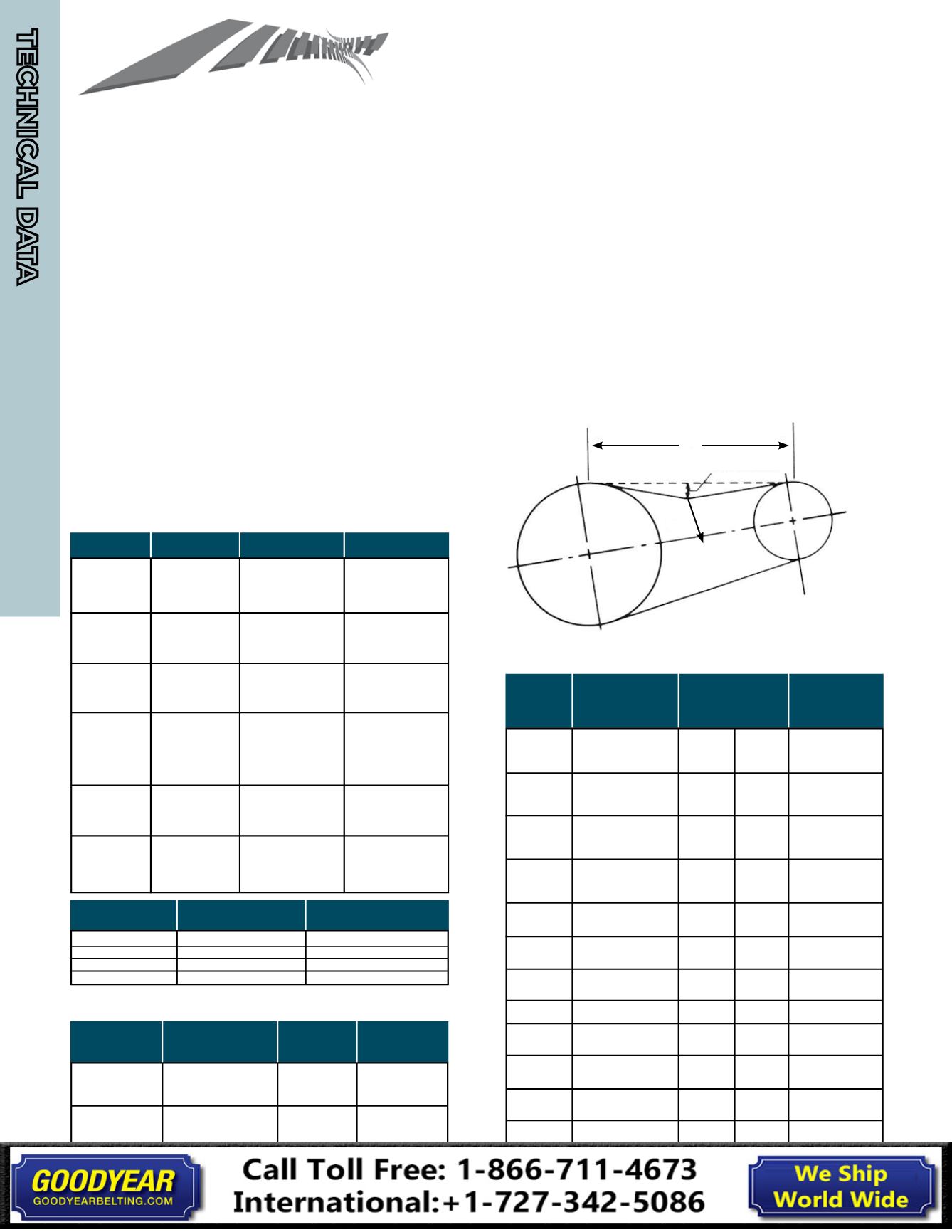
To properly tension a timing belt, place belt on pulleys and
adjust takeup until the belt teeth mesh securely with the
pulley grooves. Measure belt span “t,” then tighten belt so
that it deflects 1/64-inch for every inch of belt span when a
force as specified in the table below is applied to the top of
the belt. For belts wider than two inches, a metal or wooden
strip 3/4 to 1-inch wide should be placed across the belt.
The following range of deflection forces are normally
adequate for drive installation. Actual installation tension
required depends on peak loads, system rigidity, number of
teeth in mesh, etc.
Timing Belt Tensioning Deflection Force Table
Belt Pitch Belt Width Deflection Force Wt. (kg/m/in)
Belt Tensioning Instructions - Timing, V-Belt & Multi-Rib
V-BELT & MULTI-RIB SERIES
V-belt tensioning adjustment can be made using a tension
gauge or other type spring scale, using the following procedure.
After seating the belts in the groove and adjusting center dis-
tance so as to take up slack in the belts, further increase the
tension until only a slight bow on the slack side is apparent while
the drive is operating under load. Stop the drive and, using the
gauge, measure the force necessary to depress one of the center
belts 1/64-inch for every inch of belt span (see sketch below).
For example, a deflection for a 50-inch belt span is 50/64ths, or
25/32-inch. The amount of force required to deflect the belt
should compare with the deflection forces noted in the chart
below. Also notice for V-belts the deflection forces vary from the
initial “run-in” values, which are greater (reflecting higher run-in
tensioning) to the “normal” values for after the run-in period.
MXL
(.080-in.)
XL
(1/5-in.)
L
(3/8-in.)
H
(1/2-in.)
XH
(7/8-in.)
XXH
(1-1/4-in.)
1/8-inch
3/16-inch
1/4-inch
5/16-inch
1/4-inch
5/16-inch
3/8-inch
1/2-inch
3/4-inch
1-inch
3/4-inch
1-inch
1-1/2-inch
2-inch
3-inch
2-inch
3-inch
4-inch
2-inch
3-inch
4-inch
5-inch
1 oz
1 - 1-1/2 oz
2 oz
2 - 2-1/2 oz
2-1/2 oz
3 oz
3-1/2 oz
7 oz
11 oz
1 lb
2 lbs
2-1/2 lbs
4 lbs
5-1/2 lbs
8-1/2 lbs
7-1/2 lbs
11-1/2 lbs
16-1/2 lbs
9 lbs
14 lbs
20 lbs
26 lbs
Multi-Rib Deflection Force Table
Belt Pitch Small Sheave Force "F" Weight
Cross Section Diameter Range Lbs. Per Rib kg/m/rib
J
1.32-1.67
0.4
J
1.77-2.20
0.5 0.008
J
2.36-2.95
0.6
L
2.95-3.74
1.7
L
3.94-4.92
2.1 0.032
L
5.20-6.69
2.5
M
7.09-8.82
6.4
M
9.29-11.81
7.7 0.110
M
12.40-15.75
8.8
Span Length
t
Deflection 1/64” per inch of span
Force at center
of span
Measure the span length "t" as
shows in the sketch above.
Belt Smaller Pulley Deflection Force
Cross Diameter Range Run-In Normal Weight
Section (in.)
(lbs.) (lbs.) kg/m
3.0-3.6
3.8-4.8
5.0-7.0
3.0-3.6
3.8-4.8
5.0-7.0
3.4-4.2
4.4-5.2
5.4-9.4
3.4-4.2
4.4-5.2
5.4-9.4
7.0-9.0
9.5-16.0
7.0-9.0
9.5-16.0
12.0-16.0
18.0-22.0
21.6-27.0
3.40-4.20
4.20-10.6
2.20-3.65
4.12-10.6
7.10-10.9
11.8-16.0
4.40-10.9
11.8-16.0
12.5-17.0
18.0-22.4
3-3/8
4-1/4
5-1/8
4-1/8
5
6
4
6
7-1/8
5-1/4
7-1/8
9
11-1/4
15-3/4
13-1/2
17-1/2
24-1/2
33
48
6
7
7
8
16
20
18
22
36
40
2-1/4
2-7/8
3-3/8
2-3/4
3-1/4
4
2-5/8
4
5-1/4
3-1/2
4-3/4
6
7-1/2
10-1/2
9
11-3/4
16-1/2
22
32
4
5
5
6
8-12
10-15
10-14
12-18
18-27
20-30
A
AX
B
BX
C
CX
D
E
3V
3VX
5V
5VX
8V
Standard V-Belt Tensioning Deflection Force Table
Weight Belt
0.064
0.087
0.103
0.274
0.523
*
Belt HTB® TIGER®
*
Pitch Wt. (kg/m/mm) Wt. (kg/m/mm)
3M
0.0024
---
5M
0.0041
---
8M
0.0059
0.0063
14M
0.0102
0.0096
A = 0.13
AX = 0.12
B = 0.19
RB = 0.27/RIB
BX = 0.19
C = 0.33
RC = 0.42/RIB
CX = 0.31
D = 0.64
E = 0.98
3V = 0.08
R3V = 0.12/RIB
3VX = 0.07
R3VX = 0.09/RIB
5V = 0.20
R5V = 0.30/RIB
5VX = 0.18
R5VX = 0.23/RIB
8V = 0.59
R8V = 0.70/RIB
*See page 73 for deflection forces