


 76 / 84

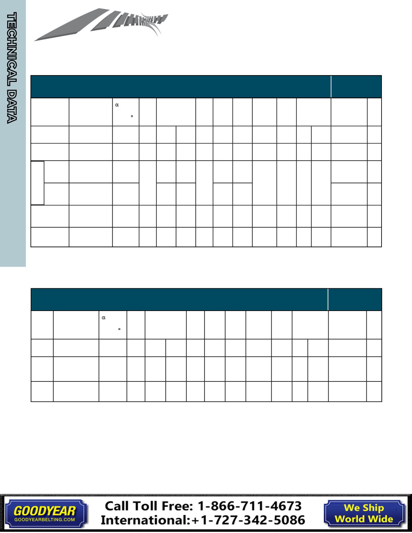
Sheave Dimension Information - According to ARPM (RMA)
Standard IP-20 (2007) (A, B, C, AX, BX, CX, AA, BB, CC)
TABLE I-1 STANDARD GROOVE DIMENSIONS
DESIGN
(INCHES)
FACTORS
Summation of the deviations from “S g ” for all grooves in any
one sheave shall not exceed ±0.050 inches.
The variation in datum diameter between the grooves in
any one sheave must be within the following limits:
Up through 19.9 inches outside diameter and up through 6
grooves : 0.010 inches (add 0.0005 in. for each additional
groove).
20.0 inches and over on outside diameter and up through 10
grooves: 0.015 inches (add 0.0005 inches for each
additional groove).
This variation can be obtained easily by measuring the distance
across two measuring balls or rods placed diametrically
opposite each other in a groove. Comparing this “diameter over
balls or rods” measurement between grooves will give the
variation in datum diameter.
Deep groove sheaves are intended for drives with belt
offset such as quarter-turn or vertical shaft drives. (See RMA
Power Transmission Belt Technical Information Bulletin IP-3-
10, V-Belt Drives with Twist.)
Joined belts will not operate in deep groove sheaves
.
Also, A and AX Joined belts will not operate in A/AX and B/BX
combination grooves.
TABLE I-1 - GROOVE DIMENSIONS - INCHES (See Figure I-1)
Standard Groove Dimensions
Design Factors
Cross Section Datum Diameter
Range
α
Groove
Angle
±0.33
°
b d
ref
b g
h g
Min
2h d
Ref
R B
Min
d B
±0.0005
S g
±0.025
S e
Minimum
Recommended
Datum
Diameter
2a p
A, AX
Up thru 5.4
Over 5.4
34
38
0.418 0.494
0.504 ±0.005 0.460 0.250 0.151
0.152
0.4375
(7/16)
0.625 0.375 +0.090
-0.062
A 3.0
AX 2.2
0
B, BX
Up thru 7.0
Over 7.0
34
38
0.530 0.637
0.650 ±0.006 0.550 0.350 0.192
0.193
0.5625
(9/16)
0.750 0.500 +0.120
-0.065
B 5.4
BX 4.0
0
A, AX
Belt
Up thru 7.4(1)
Over 7.4
34
38
(2)
0.508
0.612
0.625 ±0.006
0.612
0.634
(3)
0.602
0.233
0.229
0.5625
(9/16)
0.750 0.500 +0.120
-0.065
A 3.6 (1)
AX 2.8 0.38
B, BX
Belt
Up thru 7.4(1)
Over 7.4
34
38
0.612
0.625 ±0.006
0.268
(3)
0.276
0.233
0.229
B 5.7(1)
BX 4.3 -0.08
C, CX
Up thru 7.99
Over 7.99 - 12.0
Over 12.0
34
36
38
0.757
0.879
0.887
0.895
±0.007 0.750 0.400
0.279
0.280
0.282
0.7812
(25/32) 1.000 0.688 +0.160
-0.070
C 9.0
CX 6.8
0
D
Up thru 12.99
Over 12.99 - 17.0
Over 17.0
34
36
38
1.076
1.259
1.271
1.283
±0.008 1.020 0.600
0.416
0.417
0.418
1.1250
(1 1/8)
1.438 0.875 +0.220
-0.080
13.0
0
(1) Diameters shown for combination grooves are outside diameters. A specific datum diameter does not exist for either A or B belts in combination grooves.
(2) The b d value shown for combination grooves is the “constant width” point but does not represent a datum width for either A or B belts (2h d = 0.340 reference).
(3) 2h d values for combination groove are calculated based on b d for A and B grooves.
Deep Groove Dimensions
Design Factors
Cross
Section
Datum 1)
Diameter Range
α
Groove
Angle
±0.33
°
b d
ref
b g
h g
Min
2h d
Ref
R B
Min
d B
±0.0005
S g
±0.025
S e
Minimum
Recommended
Datum
Diameter
2a p
B, BX Up thru 7.0
Over 7.0
34
38
0.530 0.747
0.774 ±0.006 0.730 0.710 0.014
0.015
0.5625
(9/16)
0.875 0.562 +0.120
-0.065
B 5.4
BX 4.0
0.36
C, CX
Up thru 7.99
Over 7.99 - 12.0
Over 12.0
34
36
38
0.757
1.066
1.085
1.105
±0.007 1.055 1.010
-0.024
-0.022
-0.020
0.7812
(25/32) 1.250 0.812 +0.160
-0.070
C 9.0
CX 6.8
0.61
D
Up thru 12.99
Over 12.99 - 17.0
Over 17.0
34
36
38
1.076
1.513
1.541
1.569
±0.008 1.435 1.430
0.005
0.005
0.006
1.1250
(1 1/8)
1.750 1.062 +0.220
-0.080
13.0
0.83
(1) The A/AX, B/BX combination groove should be used when deep grooves are required for A or AX belts.
A,AX & B,BX
Combination
All rights reserved. The contents f this publication may not be reprinted
or otherwise reproduced in any form without the express written permission of RMA.
(1) Diameters shown for combination groove are outside diameters. A specific datum does not exist for either A or B belts in combination grooves.
(2) The b d v for combination gro ves
e "constant width" point, but does ot represent a datum width for either A or B b lts
(2h d = 0.340 reference.
(3) 2h d values for combination groove are calculated based on b d for A and B grooves.
NOTE: For Double-Sided AA, BB, CC, the minimum recommended datum diameter for A, B, C section is used.
Summation of the deviations from “S g ” for all grooves in any
one sheave shall not exceed ±0.050 inches.
The variation in datum diameter between the grooves in
any one sheave must be within the following limits:
Up through 19.9 inches outside diameter and up through 6
grooves : 0.010 inches (add 0.0005 in. for each additional
groove).
20.0 inches and er on outside diameter and up through 10
grooves: 0.015 inches (add 0.0005 inches for each
This vari tion can be obtain d easily by measur ng the distance
cross two measuring balls or rods placed diametrically
opposite each other in a groove. Comparing this “diameter over
balls or rods” measurement between grooves will give the
variation in datum diameter.
Deep groove sh aves are intended f r driv s with belt
offset such as quarter-turn or vertical shaft drives. (See RMA
Power Transmission Belt Technical Information Bulletin IP-3-
10, V-B lt Drives with Twist.)
Joined belts will not operate in deep groove sheaves
.
TABLE I-1 - GROOVE DIMENSIONS - INCHES (See Figure I-1)
Standard Groove Dimensions
Design Factors
Cross Section Datum Diameter
Range
α
Groove
Angle
±0.33
°
b d
ref
b g
h g
Min
2h d
Ref
R B
Min
d B
±0.0005
S g
±0.025
S e
Minimum
Recommended
Datum
Diameter
2a p
A, AX
Up thru 5.4
Over 5.4
34
38
0.418 0.494
504 ±0.005 0.460 0.250 0.151
0.152
0.4375
(7/16)
0.625 0.375 +0.090
-0.062
A 3.0
AX 2.2
0
B, BX
Up thru 7.0
Over 7.0
34
38
0.530 0.637
0.650 ±0.006 0.550 0.350 0.192
0.193
0.5625
(9/16)
0.750 0.500 +0.120
-0.065
B 5.4
BX 4.0
0
A, AX
Belt
Up thru 7.4(1)
Over 7.4
34
38
(2)
0.508
0.612
0.625 ±0.006
0.612
0.634
(3)
0.602
0.233
0.229
0.5625
(9/16)
0.750 0.500 +0.120
-0.065
A 3.6 (1)
AX 2.8 0.38
B, BX
Belt
Up thru 7.4(1)
Over 7.4
34
38
0.612
0.625 ±0.006
0.2 8
(3)
0.276
0.233
0.229
B 5.7(1)
BX 4.3 -0.08
C, CX
Up thru 7.99
Over 7.99 - 12.0
Over 12.0
34
36
38
0.757
79
0.887
0.895
±0.007 0.750 0.400
0.279
0.280
0.282
0.7812
(25/32) 1.000 0.688 +0.160
-0.070
C 9.0
CX 6.8
0
Up thru 12.99
Over 12.99 - 17.0
Over 17.0
34
36
38
1.076
59
1.271
1.283
±0.008 1.020 0.600
0.416
0.417
0.418
1.1250
(1 1/8)
1.438 0.875 +0.220
-0.080
13.0
0
(1) Diameters shown f r combi ati n grooves are outside iameters. A specific datum diameter does not exist for either A or B belts in combination grooves.
(2) The b d value shown for combination grooves is the “constant width” point but does not represent a datum width for either A or B belts (2h d = 0.340 reference).
(3) 2h d values for combination groove are calculated based on b d for A and B grooves.
Deep Groove Dimensions
Design Factors
Cross
Section
Datum 1)
Diameter Range
α
Groove
Angle
±0. 3
°
b d
ref
b g
h g
Min
2h d
Ref
R B
Min
d B
±0.0005
S g
±0.025
S e
Minimum
Recommended
Datum
Diameter
2a p
B, BX Up thru 7.0
Over 7.0
34
38
0.530 0.747
0.774 ±0.006 0.730 0.710 0.014
0.015
0.5625
(9/16)
0.875 0.562 +0.120
-0. 65
B 5.4
BX 4.0
0.36
C, CX
Up thru 7.99
Over 7.99 - 12.0
Over 12.0
34
36
38
0.757
1.066
1.085
1.105
±0.007 1.055 1.010
-0.024
-0.022
-0.020
0.7812
(25/32) 1.250 0.812 +0.160
-0.070
C 9.0
CX 6.8
0.61
D
Up thru 12.99
Over 12.99 - 17.0
Over 17.0
34
36
38
1.076
1.513
1.541
1.569
±0.008 1.435 1.430
0.005
0.005
0.006
1.1250
(1 1/8)
1.750 1.062 +0.220
-0.080
13.0
0.83
(1) The A/AX, B/BX combination groove should be used when deep grooves are required for A or AX belts.
A,AX & B,BX
Combination
All rights reserved. The contents of this publication may not be reprinted
or otherwise reproduced in any form without the express written permission of RMA.
TABLE I-1 DEEP GROOVE DIMENSIONS
DESIGN
(INCHES)
FACTORS
Su ation of the deviations from "S g " for all grooves in any one sheave shall not exce d ±0.050 inches.
The variation of datum diameter between the grooves in any one sheave must be within the following limits:
Up to 19.9 inches outside diameter and up through 6 grooves: 0.010 (add 0.0005 in. for each additional groove).
20.0 inches and over on outside diameter and up through 10 grooves: 0.015 inches (add 0.0005 inches for each
additional groove).
This variation can be obtained easily by measuring the distance across two measuring balls or rods placed diametrically
opposit eac other in a groov . Co pari g this "diameter over balls and rods" measurement between grooves will
give the variation in datum diameter.
Deep groove sheaves are intended for drives with belt offset such as quarter-turn or vertical shaft drives. (See RMA
Power Transmission Belt Technical Information Bulletin IP-3-10, V-Belt Drives with Twist.)
Joined belts will not operate in deep groove sheaves.
Also, A and AX Joined Belts will not operate in A/AX and B/BX
combination grooves.
(1) The A/AX, B/BX combination groove should be used when deep grooves are required for A or AX belts.
RMA IP-20 (2007)
Part 1 (Inch-Pound Units)
TECHNICAL DATA
POWERING GLOBAL INDUSTRY
TECHNICAL DATA
74