


 148 / 235

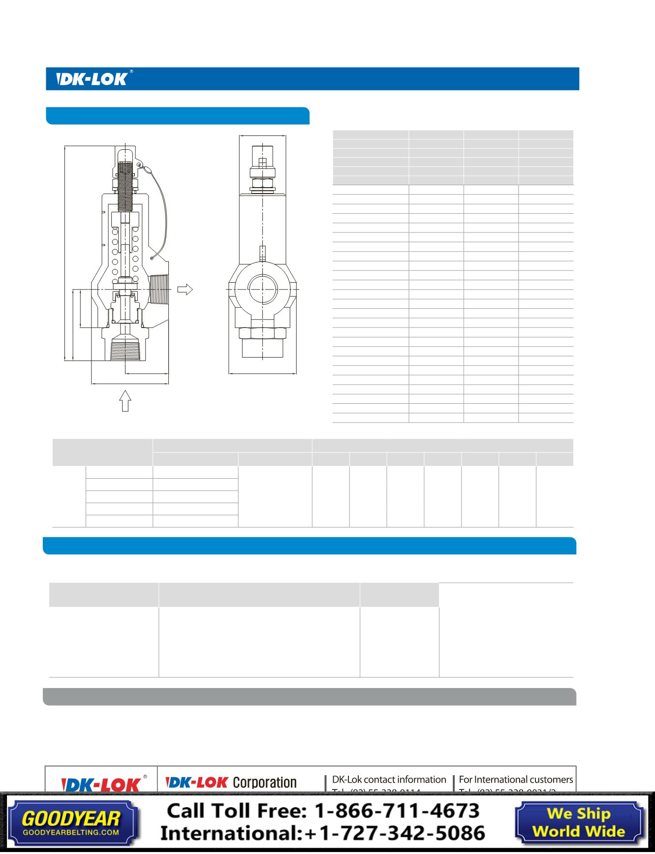
V64 Series
Relief Valves
OUTLET
INLET
H
H1
L1
D1
D
L
H2
Ordering Number and Dimensions
Table 3.
Flow Rate
Flow rate measured by overpressure of 110% or 3 psig.
Media
Air
Gas
Water
Density
0.0764
0.0458
62.306
SG
1
0.6
1
Temp.
60 °F
60 °F
70 °F
Factor
Kd Factor 0.838 Kd Factor 0.838 K Factor 0.62
Set Pressure psig (bar)
SCFM
SCFM
GPM
15 (1.03)
64
80
13
20 (1.3)
74
93
14
25 (1.7)
84
105
16
30 (2.0)
94
117
17
50 (3.4)
137
171
22
100 (6.8)
245
306
32
150 (10.3)
353
441
39
200 (13.7)
462
576
45
250 (17.2)
570
711
50
300 (20.6)
678
846
55
400 (27.5)
894
1117
63
500 (34.4)
1111
1387
71
600 (41.3)
1327
1657
77
700 (48.2)
1543
1927
84
900 (62.0)
1976
2467
95
1000 (68.9)
2192
2737
100
1500 (103)
3274
4088
122
1750 (120)
3815
4763
132
2000 (137)
4355
5438
141
2500 (172)
5437
6789
158
3000 (206)
6519
8139
173
4000 (275)
8682
10840
200
4500 (310)
9763
12191
212
5000 (344)
10845
13541
224
5500 (379)
11927
14892
235
Table 4.
Basic Ordering Number and Dimensions
Basic Ordering Number
End Connections
Dimensions in. (
mm
)
Inlet
Outlet
H
H1
H2
L
L1
D D1
V64-
F8N16N-
1/2 in. Female NPT
1 in. Female NPT 9.25
(
235
)
3.07
(
78.0
)
1.64
(
41.8
)
3.32
(
84.50
)
1.87
(
47.5
)
2.00
(
51.0
)
2.36
(
60.0
)
F12N16N-
3/4 in. Female NPT
MF8N16N-
1/2 in. Male NPT
MF12N16N-
3/4 in. Male NPT
MF16N-
1 in. Male NPT
Ordering Information
Safe Valve Selection
Select the desired valve basic ordering number in the table 4, applicable O-Ring designator, Spring designator, and Valve body
material in the table below.
O-Ring Material Designators
Spring Set Pressure Designators Unit: psig
Valve Body Material
Designators
Example of a complete ordering
Number.
V64-F12N16N-
EP-8-C
Factory Set Valve
To order, specify the set pressure on
the valve ordering number.
i.e., V64-F-8N16N-
1200
-C
Applicable to components
number of 14, and 16
in the table 1.
• Nil: Standard FKM O-Ring
• HBN: HNBR
• EP: EPDM
• C: Carbon Steel
• S: Stainless Steel
The selection of a valve for any application or system design must be considered to ensure safe performance.
Valves function, valve rating, material compatibility, proper installation, operation and maintenance remain the sole responsibility
of the system designer and the user. DK-Lok accepts no liability for any improper selection, installation, operation or maintenance.
© Copyright 2010-2013. All Rights Reserved.
• 1 : 15-40(Brown)
• 2 : 41-100(Light Blue)
• 3 : 101-215(Yellow)
• 4 : 216-350(Light Green)
• 5 : 351-750(Red)
• 6 : 751 - 1000(Orange)
• 7 : 1001 - 1800(Silver)
• 8 : 1801 - 2800(Black)
• 9 : 2801 - 3700(Non)
•10 : 3700 - 5500(Dark Brown)