


 144 / 235

Technical Data
V61 Series Spring Cracking Pressure Range Designator
Factory Test
How to Order
Designator
Cracking pressure range
@20°C(70°F)
Standard set cracking pressure
(The Middle point setting)
psig
bar
psig
bar
1
0.5 - 2.5
0.03 - 0.17
1.6
0.11
5
2.6 - 7.5
0.18 - 0.51
5.0
0.34
10
7.6 - 15
0.52 - 1.03
11.5
0.79
20
16 - 35
1.1 - 2.41
26
1.79
50
36 - 75
2.48 - 5.17
56
3.86
100
76 - 125
5.24 - 8.61
100
6.89
150
126 - 150
8.68 - 10.4
138
9.5
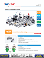
Every valve is factory tested for cracking and performance.
According to system line’s requested pressure,
Turn the locknut(with JIG as picture.1)as picture and set the
cracking pressure.
Seal Material Designator
Spring Nominal Cracking Pressure Designator
Valve Body Material Designator
●
FKM : Nil for SS316 Valve
●
NBR : Nil for Brass Valve
●
FKM : VT
●
NBR : BN
●
EPDM : EP
●
FFKM : KZ
“Note: Select the spring designtor
1 ,5, 10, 20, 50, 100, 150”
●
S : 316 stainless steel
●
B : Brass
VENT Relief valve
Select valve basic ordering number, applicable seal, spring nominal cracking pressure, and body material.
V61 -
NIL-
1-
S
KZ-
B
EP-
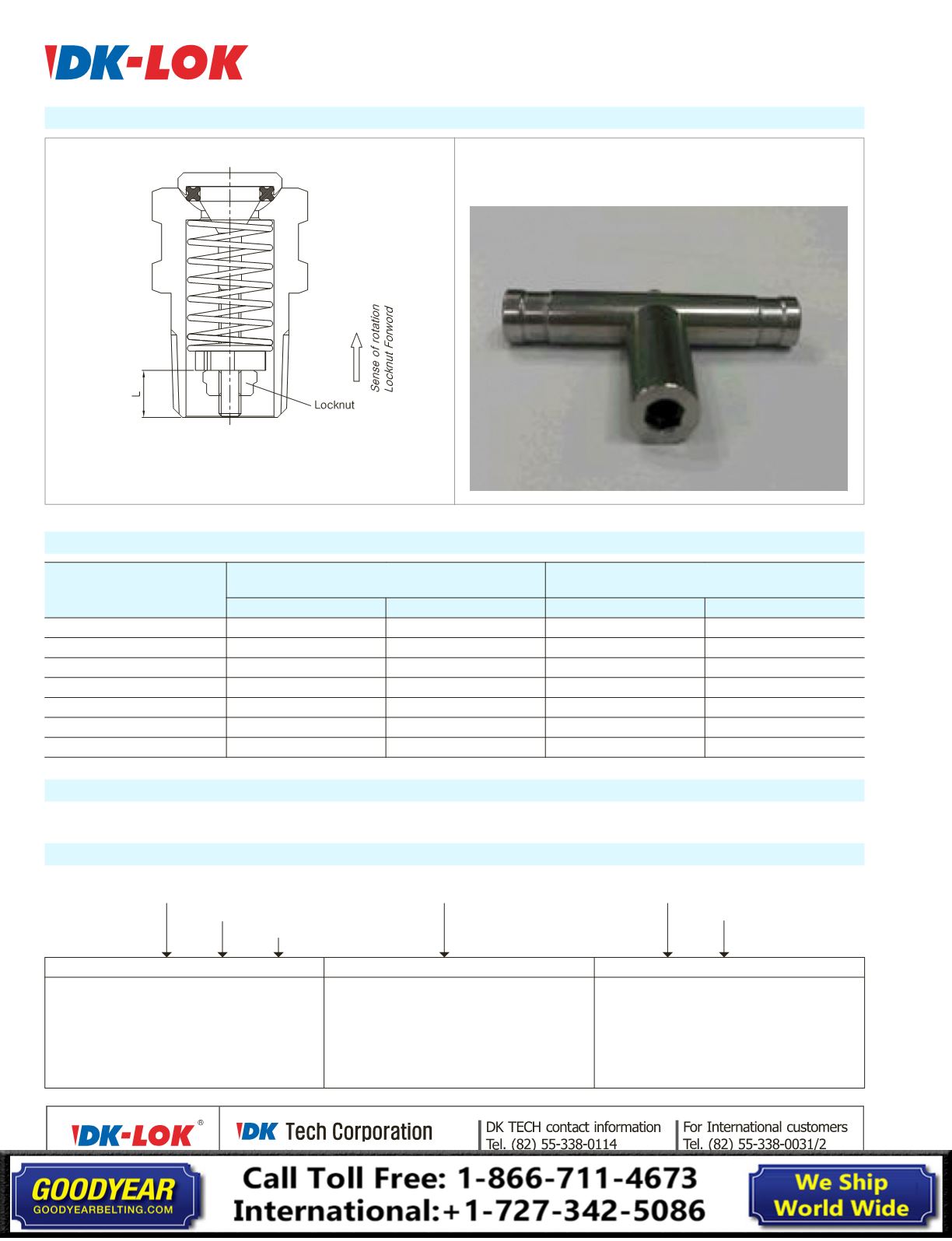
JIG Reference <picture.1>