


 146 / 235

V63&V66 Series
Relief Valves
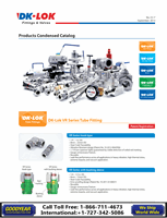
Ordering information and Dimensions
How to order
Safe Valve Selectionn
Please select the desired valve basic ordering number, the applicable
seal, spring designator and CE certified option from the table below.
Example : V66-D-4T
- BN
- B
- CE
Seat Designator
Spring Designator
CE certified
Nil
: Standard Viton
BN
: Buna N
EP
: EPDM
Refer to Table 1,
Table 2 for spring
designator
CE
: valve to
97/23/EC
The selection of a valve for any application or system design must be considered to ensure safe performance. Valve function, valve
rating, material compatibility, proper installation, operation and maintenance remain the sole responsibility of the system designer
and the user. DK-Lok accepts no liability for any improper selection, installation, operation or maintenance.
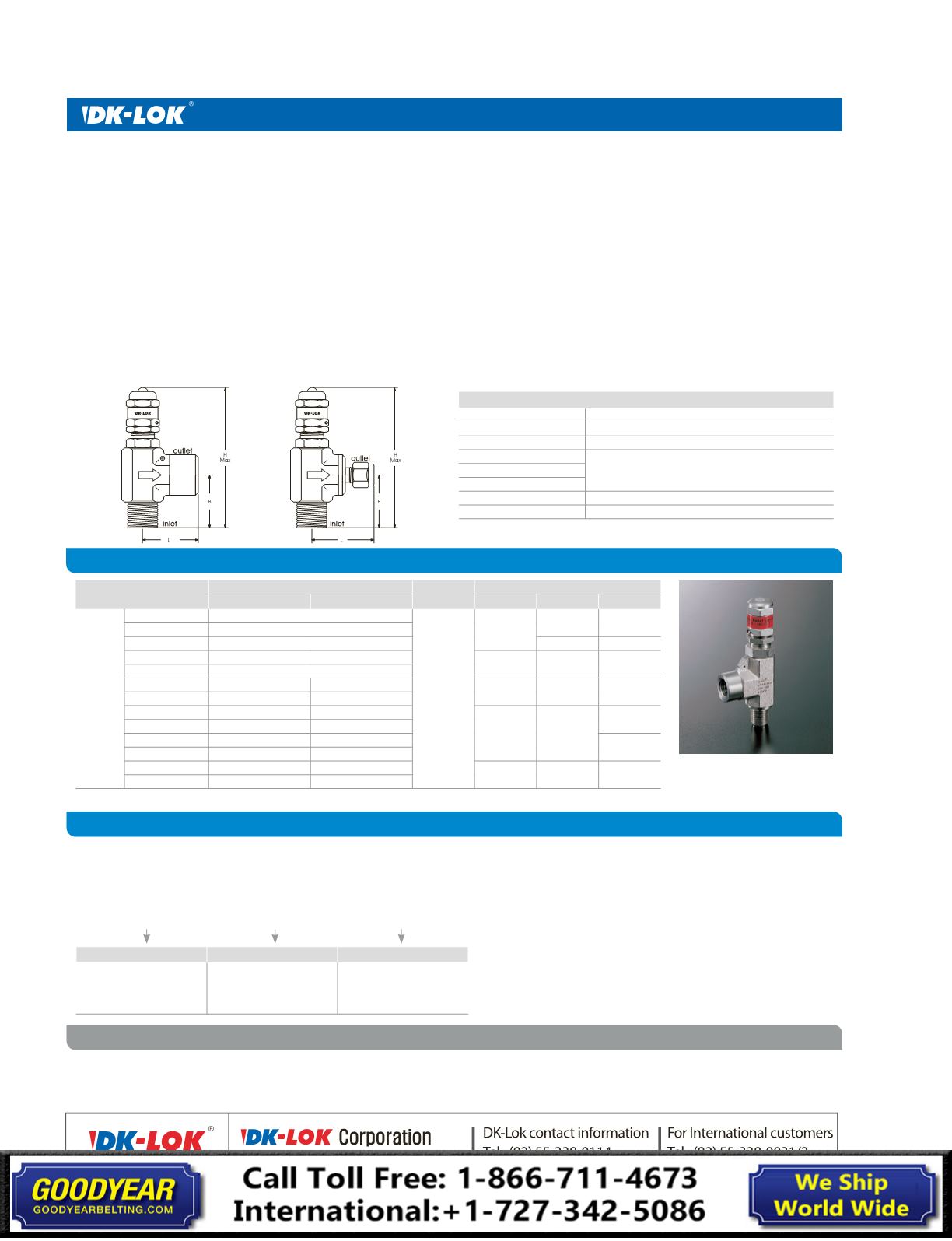
Model Shown :
V66-MF-4N-A
Factory pressure set valve
To order, specify the set pressure on the valve ordering number.
Example : V66-D-4T-60BAR or V66-D-4T-870PSI
Valve without spring installed
To order, do not specify spring designator on the ordering number.
Example : V66-D-4T
Note
: The valve with no spring installed is supplied with the label
stated“NO SPRING INSTALLED”on the adjusting cap.
Spring for field assembly
To order, select an applicable spring from the spring designator table
1 & 2. Spring kit includes spring, sticker and wire Example : RVS-A
HowTo Adjust Valve Cracking Pressure
The valve user shall set a specific cracking pressure of the valve
supplied.
1. To increase the cracking pressure of the valve, turn the adjusting cap
clockwise to compress the spring.
2. To reduce the cracking pressure, turn counterclockwise.
3. Start the pump with the spring relaxed (eight threads showing
with the Locking Nut at bottom), with the discharging port open,
check the gauge pressure as you turn the adjusting cap clockwise to
increase the pressure to the desired operating range.
4. If the system has more than one outlet, set the valve pressure with
one outlet open, and then check again with all outlets open to make
sure that the set pressure is within the desired operating range.
5. Set the Locking Nut and the wire tomaintain the set cracking pressure.
All dimensions shown are for reference only and are subject to change. Dimensions with DK-Lok nuts are in finger-tight position.
Operation
• Install the valve between the pump outlet as close as possible, and any shut-
off device in the discharge line.The preferablemounting position is vertical
with the adjusting cap at the top.
• D-Pro relief valve bypasses the system fluid to prevent instrument or sensitive
gauge in the system fromexcess pressure.
• When the inlet pressure overcomes the set spring pressure on the poppet,
the poppet lifts off the valve seat, allowing flow to bypass and thereby
balance the systempressure.
• If the valve has not been actuated for a period of time, it may initially crack
above the set cracking pressure.
• Cracking pressure is only sensitive to inlet pressure, and is not affected by
outlet pressure.
• Cv reduction : Valve flowmay be reduced by the restriction of pipe and
tubing connected.
Material of Construction
Cap Plug
Polypropylene
Adjusting Cap
ASTM A276 / A479 Type 316
Spring
Stainless Steel 302
Locking Nut
ASTM A276 / A479 Type 316
Bonnet
Poppet
Stem & O-ring seal
Standard Viton, optional EPDM and Buna N
Body
ASTM A182 F316
Basic Ordering Number
End Connections
Orifice
mm (
in.
)
Dimensions mm (
in.
)
Inlet
Outlet
H
B
L
V63-
and
V66-
D-4T-
1/4 DK-Lok
V63 :
4.8 (
0.19
)
V66 :
3.4 (
0.13
)
100 (
3.93
) 37 (
1.45
)
39 (
1.53
)
D-6M-
6 mm DK-Lok
D-8M-
8 mm DK-Lok
38 (
1.49
)
40 (
1.57
)
D-8T-
1/2 DK-Lok
105 (
4.13
) 44 (
1.73
)
42 (
1.65
)
D-12M-
12 mm DK-Lok
MD-8N8T-
1/2 Male NPT
1/2 DK-Lok
98 (
3.85
)
36 (
1.41
)
42 (
1.65
)
MD-8N12M-
1/2 Male NPT 12 mm DK-Lok
MF-4N-
1/4 Male NPT 1/4 Female NPT
94 (
3.70
)
32 (
1.25
)
30 (
1.18
)
MF-4R-
1/4 Male ISO 7/1 1/4 Female ISO 7/1
MF-6N-
3/8 Male NPT 3/8 Female NPT
35 (
1.37
)
MF-6R-
3/8 Male ISO 7/1 3/8 Female ISO 7/1
MF-8N-
1/2 Male NPT 1/2 Female NPT
98 (
3.85
)
36 (
1.41
)
38 (
1.49
)
MF-8R-
1/2 Male ISO 7/1 1/2 Female ISO