


 36 / 60

Check that the teeth of both sprockets are pointing in the
same direction when installing SilentSync® sprockets.
Snug the capscrews so that the sprocket/bushing assembly can
still move on the shaft.
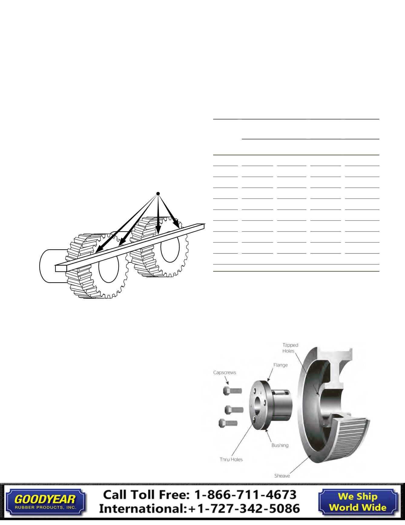
Align the sprockets using a straight edge. Check for contact in
four places as shown. Do not use bearings or drive shafts as
reference points for sprocket alignment.
Using a torque wrench, tighten the capscrews to the torque
values listed below. If there is not a gap of 1/8 inch to 1/4 inch
between the bushing flange and the sprocket hub then
disassemble the parts and determine the reason for the
faulty assembly.
The sprocket will draw onto the bushing during tightening.
Always recheck alignment after tightening the capscrews.
If alignment has changed, loosen the capscrews and move
sprocket/bushing assembly on shaft to realign. Tighten the
setscrews over the keyway to the torque values listed in
the table.
If the sprockets are straight bore, use the above alignment
procedure and then tighten the setscrews to the correct torque
for the setscrew size as listed in Table 17.
QD® bushings can be installed with the capscrews on either
side, excluding QT, M and N sizes. Drives with opposing shafts
require one of the sprockets to be mounted with the capscrews
on the flange side and one with the capscrews on the hub side.
4. How to remove a sprocket with a QD® hub
Place two of the pull-up bolts in the tapped holes in
the sprocket.
Turn the bolts alternately and evenly. They will push against the
bushing flange and act as jackscrews to break the grip between
the bushing and the hub.
Contact Points
Table 17 Torque Specifications
Bushing
Capscrew Torque
Setscrew
Torque
Setscrew
Size
(in.-lb.)
(ft.-lb.)
(in.-lb.)
(in.)
H
108
9
SH
108
9
87
1/4
SDS
108
9
87
1/4
SK
180
15
87
1/4
SF
360
30
165
5/16
E
720
60
290
3/8
F
900
75
290
3/8
J
1620
135
290
3/8
M
2700
225
290
3/8
N
3600
300
620
1/2
36
Synchronous Belts
Installation Guide