


 60 / 103

60
Tel: +1.314.739.9191 • +1.800.288.2726 • Fax: +1.314.739.5880 •
www.tapcoinc.comLF
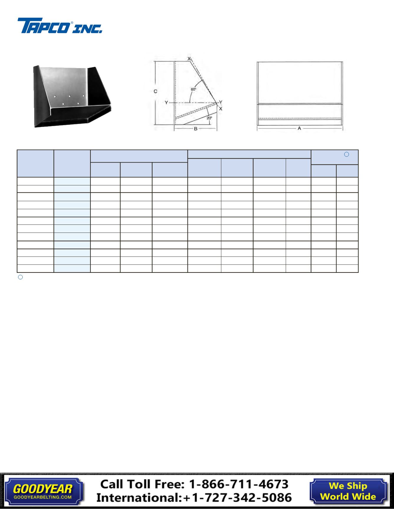
FABRICATED Steel
Elevator Buckets
INDUSTRIAL STYLE FOR HANDLING:
STONE, FOUNDRY SAND, SAND & GRAVEL, COAL, FERTILIZER, CLAY, SALT, ETC.
FEATURES:
HAS A LOW FRONT DESIGNED for inclined BUCKET elevators and TO
HANDLE FINELY PULVERIZED OR WET MATERIALS.
TECHNICAL INFORMATION:
STYLE LF Buckets
USABLE CAPACITY:
Tapco recommends using 75% of gross,
(100%) capacity.
SPACING:
Contact Tapco for recommendations.
INTERCHANGEABILITY:
Can be intermixed with existing fabricated LF
style buckets. If different weight buckets are mixed in, some care should
be taken that the leg does not become too far out of balance. Check
elevator for proper clearances. Contact Tapco for recommendations.
INSTALLATION:
On belt:
Fanged elevator bolts and nylon insert lock
nuts are recommended.
Flat steel washers must be placed inside
the bucket under the nuts.
On chain
: Use Grade 5 hex head bolts with hex nuts, flat washers,
and lock washers.
Elevator bolts should not be used on chain
attachments.
CAUTION:
Welding and cutting on elevator legs without taking
proper precautions is extremely dangerous and can cause a violent
explosion.
STYLE:
LF (Low Front).
DESIGN:
Slow speed continuous discharge.
material:
Carbon Steel, Stainless Steel, Aluminum.
METHOD OF MANUFACTURE:
Fabricated.
STANDARD CONSTRUCTION:
The LF style bucket utilizes a 2-piece
design consisting of a pressed formed body and a front plate. All
seams are continuously welded outside and partially inside.
The
bucket will be produced after Tapco supplies a CAD drawing to
be approved by customer.
CONSTRUCTION OPTIONS:
AR plate, wear lips, or hard bead welds.
MATERIAL THICKNESS:
12 ga., 10 ga., 7 ga. (3/16”), 1/4”, 5/16”, 3/8”,
and 1/2”.
DRILLING:
No charge for standard belt or chain drillings.
VENTING:
Available on request, contact Tapco for recommendations.
10
12
10
12
14
12
16
20
18
16
20
24
6
6
7
7
7
8
8
8
10
12
12
12
9-1/4
9-1/4
11-5/8
11-5/8
11-5/8
11-5/8
11-5/8
11-5/8
15
17-5/8
17-5/8
17-5/8
6.8
7.8
8.5
9.6
10.7
11.2
13.6
15.9
-
-
-
-
8.8
10.0
10.8
12.3
13.7
14.4
17.4
20.5
25.4
29.3
33.9
38.5
12.1
13.8
15.1
17.1
19.1
20.1
24.3
28.5
35.0
40.7
47.1
53.5
-
-
-
22.8
25.5
26.8
32.4
38.0
46.5
53.6
62.0
70.5
.03
.04
.05
.06
.07
.08
.10
.13
.18
.23
.29
.35
.17
.20
.24
.30
.34
.35
.46
.57
.94
1.09
1.36
1.64
Length
A
Proj.
B
Dimensions-Actual (Inches)
Tolerance A, B & C
±
1/4"
12 Gauge
Steel
10 Gauge
Steel
3/16"
Steel
1/4"
Steel
Grossx-x
Cu. Ft.
Size
(Nominal)
Inches
Size
(Nominal)
Millimeter
10 X 6 X 9
12 X 6 X 9
10 X 7 X 11
12 X 7 X 11
14 X 7 X 11
12 X 8 X 11
16 X 8 X 11
20 X 8 X 11
18 X 10 X 15
16 X 12 X 17
20 X 12 X 17
24 X 12 X 17
Weight, Pounds (Est.)
260 X 160 X 230
300 X 160 X 230
260 X 180 X 280
300 X 180 X 280
350 X 180 X 280
300 X 200 X 280
400 X 200 X 280
500 X 200 X 280
450 X 260 X 370
400 X 300 X 425
500 X 300 X 425
600 X 300 X 425
Depth
C
y-y
Cu. Ft.
AVAILABLE THROUGH INDUSTRIAL DISTRIBUTORS, CONTRACTORS, AND ORIGINAL EQUIPMENT MANUFACTURERS
End View
Back View
Capacity 1
Tolerance
±
3%
1
Tapco recommends using gross x .75, for usable capacity.