


 21 / 48

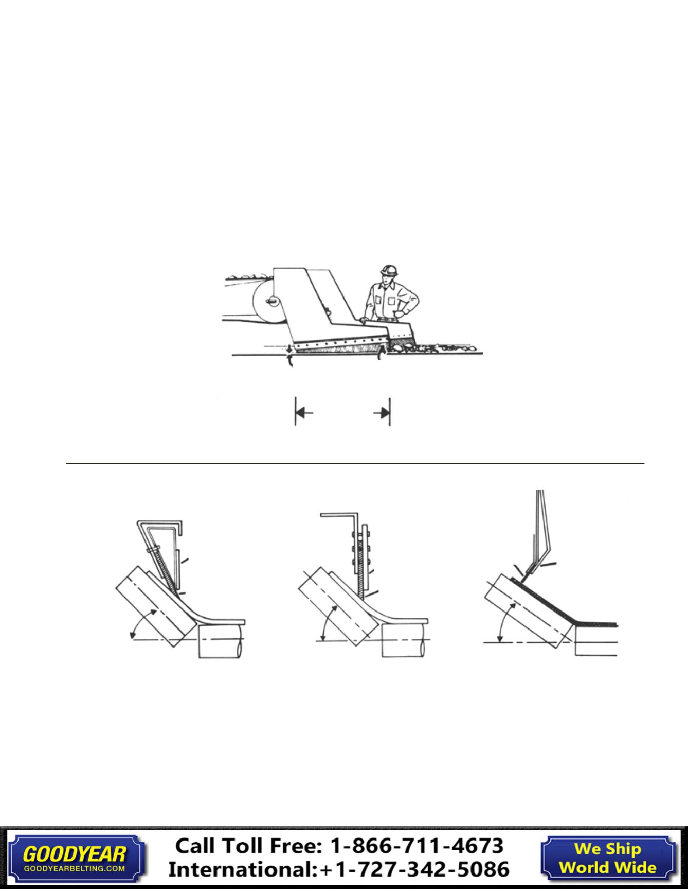
Fig. 24
1" Minimum Increasing in
Direction of Travel
Usually
4 to 5 x
Belt Width
Fig. 25
Method A
Backup Plate
Skirt Board
Rubber Held in
Compression
Variable
Idler
Angle
Variable
Idler
Angle
Method B
Backup Plate
Skirt Board
Rubber Held
in Compression
Variable
Idler
Angle
Method C
Backup Plate
Skirt Board
Rubber
An attempt to approach the above “ideal condition” should
be made continually by adjusting the chute arrangement.
Optimum loading and transferring through chutes still requires
considerable experimental adjustment in the field.
Skirt boards should be used to further center and settle the
load as it leaves the loading point. The steel structure of the
chute and skirts never should be placed closer to the surface
of the belt than 1”;
this distance to be made increasing in the
direction of belt travel to free any material trapped between
the belt surface and the skirt (Fig. 24).
Skirt boards are usually
4 or 5 times the belt width in length, but may vary considerably
due to belt speed, type of material and lump size.
Sample skirt
board arrangements are shown in Fig. 25.
Sample Skirt Board Arrangements
18
Installation, Maintenance & Troubleshooting Guide
Installation