


 20 / 48

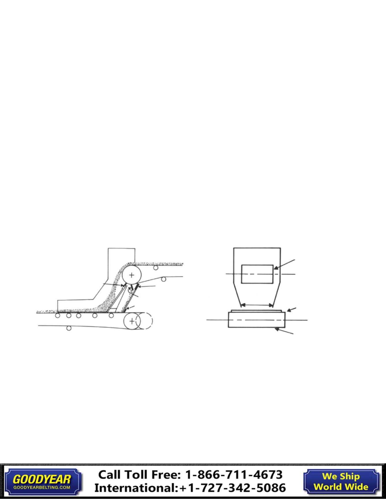
Fig. 23
Rubber Lip
Rubber Lip
Belt Wiper
Dribble Chute
Head Pulley
of Discharge Belt
Tail Pulley of
Receiving Belt
2/3 Width of
Receiving Belt
Receiving Belt
Loading
Receiving material off center will cause
the belt to move sideways after loading,
as the center of the load seeks the lowest
point in the troughing idlers.
This can be
corrected by proper chute arrangement
provided, of course, that the belt is
centered as it enters the loading point
(Fig. 23).
The loading point of any conveyor is
nearly always the critical point or the
life-determining point of the belt. Here,
the conveyor receives its major abrasion
and practically all of its impact. The “ideal
condition” is to have the material pass
from chute to belt, at the same speed
and direction of travel as the belt and
with a minimum amount of impact.
The subject of chute design and
arrangement is too broad to be
discussed in detail here. In lieu of such
discussion, the following suggestions are
offered:
The width of the receiving end of the
loading chute should be great enough
to accept material lying on the extreme
edge of the preceding belt or feeder, and
its position determined by the trajectory
of the material coming into it. At no place
should the chute be less than twice the
size of the largest lumps, if fines are
present, and 3.5 times the size of lumps,
if uniform.
The discharge width of the
chute thus determined should not
exceed about 2/3 of the receiving belts’
width (Fig. 23).
The slope of the chute is determined by
the nature of the material, its entering
velocity and length of the chute. This
value varies with each particular
installation, but about 35 degrees has
been found satisfactory for most dry
industrial materials such as coal and rock.
Simple Conveyor Loading Point
17
Installation, Maintenance & Troubleshooting Guide
Installation