


 337 / 360

2015 Power Transmission Products
General Information
156
Torque Specifications
Bushing
Capscrew Torque
Setscrew Torque
(in.-lb.)
Setscrew Size
(in.)
in.-lb.
ft.-lb.
H
108
9
–
–
SH
108
9
87
1/4
SDS
108
9
87
1/4
SK
180
15
87
1/4
SF
360
30
166
5/16
E
720
60
290
3/8
F
900
75
290
3/8
J
1620
135
290
3/8
M
2700
225
290
3/8
N
3600
300
620
1/2
Sprocket and bushing installation
9.
Using a torque wrench, tighten the capscrews to the torque
values listed below. If there is not a gap of 1/8 to 1⁄4 inch
between the bushing flange and the sprocket hub, then
disassemble the parts and determine the reason for the
faulty assembly.
10.
The sprocket will draw onto the bushing during tightening.
Always recheck alignment after tightening the capscrews.
If alignment has changed, return to Step 7 (on page 153).
11.
Tighten the setscrews over the keyway to the torque
values listed in the table below.
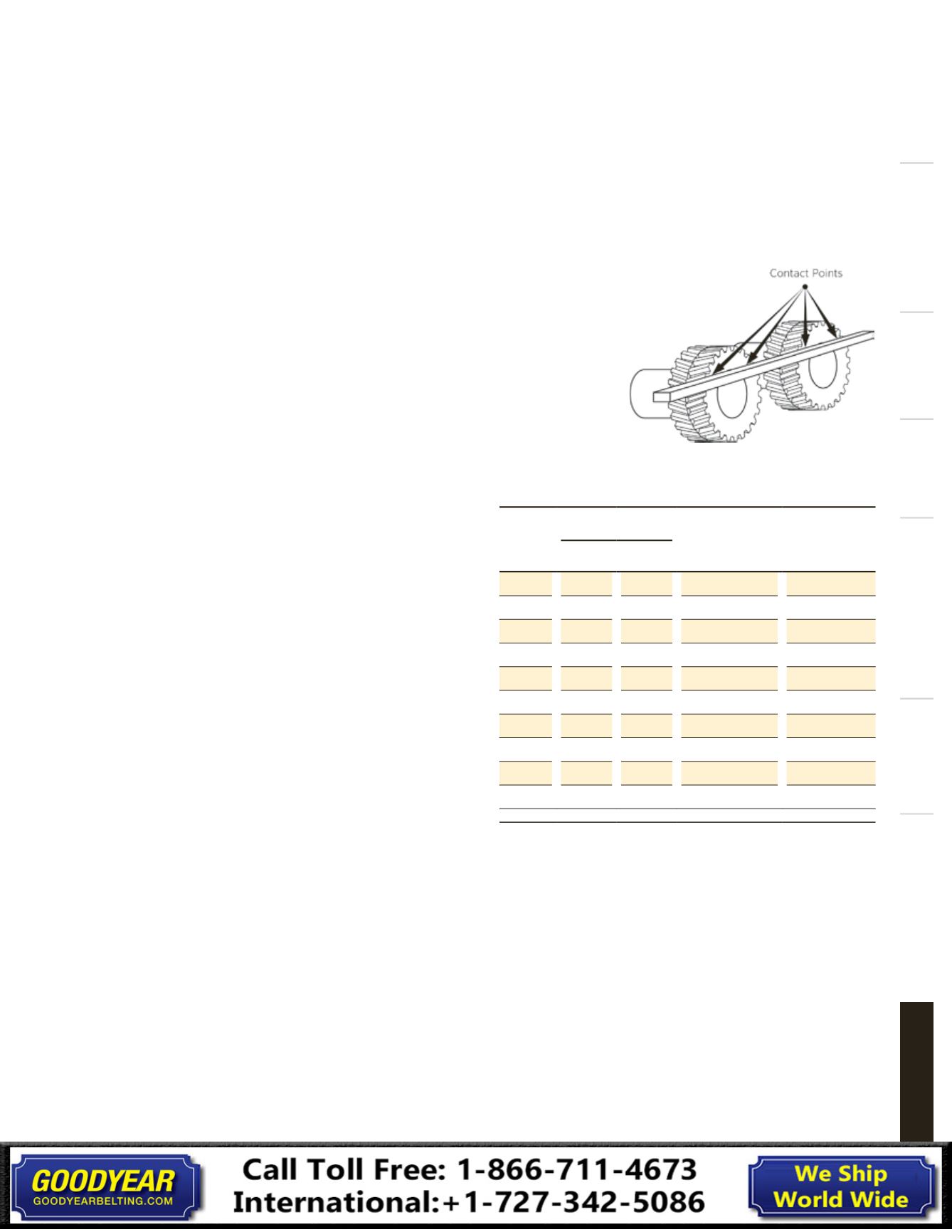
12.
If the sprockets are straight bore, use the above alignment
procedure and then tighten the setscrews to the correct torque
for the setscrew size listed in the Torque Specifications table.
QD® bushings can be installed with the capscrews on either
side, excluding H, M and N sizes. Drives with opposing shafts
require one of the sprockets be mounted with the capscrews
on the flange side and one with the capscrews on the hub side.
Overview
Synchronous
Banded
V-Belt
Bushing Hardware
Specialty
Automotive & Truck
General Information