


 336 / 360

2015 Power Transmission Products
General Information
155
Preparation
OBJECTIVE:
Verify that all necessary tools and parts are
available and ready for installation.
1.
SilentSync® belts and sprockets are identified with a
unique Color Spectrum System. The seven colors used for
identification are Yellow, White, Purple, Blue, Green, Orange and
Red. Each color represents a different size so that Blue belts
are made to operate with Blue sprockets. Make sure the same
color belt and sprockets have been obtained. When installing
Falcon Pd,® Hawk Pd® and Blackhawk Pd,® it is also important
that the correct sprocket width is used.
2.
The following tools are recommended for proper belt and
sprocket installation.
›
Straightedge
›
Tape measure
›
Socket and open end wrenches
›
File and sandpaper
›
Torque wrench
›
Clean cloth
›
Belt tension gauge
›
Deflection force values
›
Laser Alignment
for tensioning the belt
3.
Make sure the components are ready for installation.
Clean all shafts, removing any nicks or burrs. Clean all mating
surfaces of the sprocket, bushing and shaft. No lubrication or
anti-seize solution should be used on any of these surfaces,
including threaded holes. Use of lubrication can create higher
torque, which will cause premature failure.
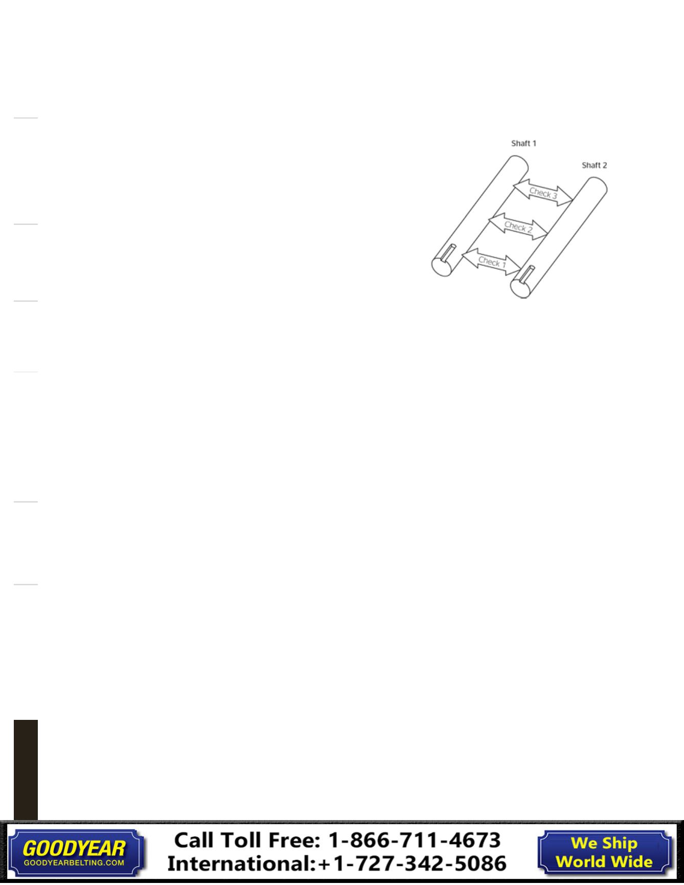
4.
Make sure the shafts are true and parallel by accurately
measuring the distance between the shafts at three points
along the shaft. The distance between the shafts should be the
same at all three points as shown. Also make sure the shafts are
rigidly mounted. Shafts should not deflect when the belt
is tensioned.
Sprocket and bushing installation
OBJECTIVE:
Verify that all necessary tools and parts are avail-
able and ready for installation.
1.
For conventional mounting, insert bushing into the sprocket,
aligning the tapped holes in the bushing flange with the drilled
holes in the sprocket hub.
2.
Insert capscrews through the drilled holes and into the
tapped holes.
3.
Insert the key into the keyseat of the shaft.
4.
With capscrews to the outside, place the sprocket and
bushing assembly on the shaft, positioning the assembly
with the bushing flange towards the shaft bearings. Reverse
mounting the “Quick Detachable” (QD) bushing can be
advantageous for some applications.
5.
Repeat Steps 1 through 4 for the other sprocket.
6.
Check that the teeth of both sprockets are pointing in the
same direction when installing SilentSync® sprockets.
7.
Snug the capscrews so that the sprocket/bushing
assembly can still move on the shaft.
8.
Align the sprockets using a straightedge. Check for
contact in four places as shown. Do not use bearings or drive
shafts as reference points for sprocket alignment. Continental
ContiTech Laser Alignment Tool provides an alternative method
for checking alignment.
See pages 172-174 for tools offered and how to order.
Technical Information
Sprocket installation
Follow all safety policies and requirements of federal, state
and local authorities, as well as the regulation of the employer,
when working on power equipment. Always lock out the
power source to the machinery before performing any work.
General Information
Automotive & Truck
Specialty
Bushing Hardware
V-Belt
Banded
Synchronous
Overview