


 173 / 235

 www.dklok.com
Valves
DK-LokTubeFittingCerti cationListing
DK-LokValveCerti cationListing
QualitySystemApprovals
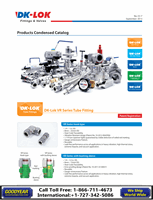
Wrench Actuation
on STEM HEX HEAD
OPEN
20.6mm
0.81inch
h
7/16"
HEX
D
Hole on STEM HEAD
for bar handle
STEM THREAD
and STEM TIP
Hard chrome plate
for extended service
life and to improve
seal-ability
BODY
VENT TUBE
bleeds gas or liquid
form system
BACK STOP SCREW
with hollow hex 2.5mm
keeps STEM from
accidental disassemble
L1
L
VBV Series Bleed Valves
Design and Applications
Installation and Operation
Materials of Construction
Ordering Number and Table of Dimensions
CNG Certifications
How to Order
Technical Data
Options
Factory Test
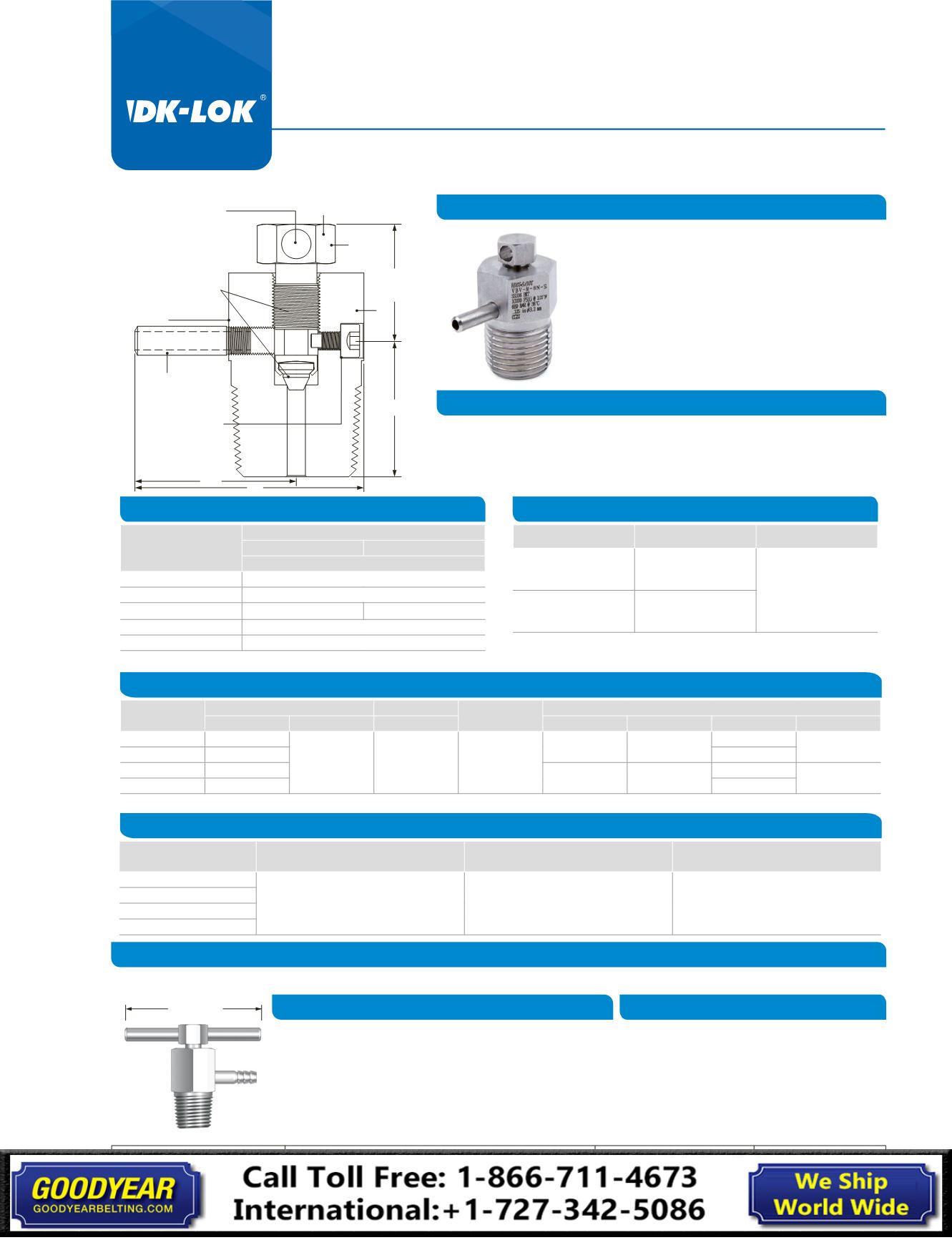
DK-Lok VBV Series Bleed Valves are designed to
vent the signal line pressure to atmosphere
before an instrument is removed and to assist in
calibration of control devices.
These are for use on instrumentation devices such
as gauge root valves and multi-valve manifolds.
Optional barbed vent tube enables containment
of fluid vented. The VBV Series are also ideal in
bleeding hydraulic systems.
Position the vent tube so that systemfluid is not directed to personnel operating.
Slowly open the valve. This valve has no stem seal packing;
small amounts of fluid will go through the stem thread when they are opened.
Therefore suitable measures should be taken to protect personnel operating.
* Carbon Steel bodies are white galvanized for corrosion resistance.
Components
VALVE BODY MATERIALS
SS316 Stainless
Carbon Steel
GRADE / ASTM and JIS SPECIFICATION
Stem
SS316 / A 276
StemTip
S630 / A564
Body*
SS316 / A 276
S20C-S45C / G4051
Back Stop Screw
SS316 / A 276
Vent Tube
SS316 / A 269
Basic
Ordering No.
End Connection
Orifice
Cv
Dimensions in. (mm)
Inlet
Outlet
in.(mm)
L
L1
D
h Hex
VBV-M-2N-
1/8" Male NPT
O.D.
3/16”
Tube Stub
0.125
(3.2)
0.25
1.34
(34.03)
0.94
(23.87)
0.75 (19.05)
5/8
(15.87)
VBV-M-4N-
1/4”Male NPT
0.69 (17.52)
VBV-M-6N-
3/8”Male NPT
1.47
(37.33)
1.03
(26.16)
0.75 (19.05)
7/8
(22.22)
VBV-M-8N-
1/2”Male NPT
0.69 (17.52)
All dimensions shown are for reference only and are subject to change.
Certificates
ECE R110
ANSI / AGA NGV 3.1-1995
CGA NGV 12.3-M95
ISO 15500
Certificate No
110R-000197
Class 0
-40°C to 120°C (-40°F to 250°F )
200 bar @ 120°C
2010-REPORT-030 (01)
CNG-VBV
-40°C to 121°C (-40°F to 250°F )
273 bar @ 121°C
2010-REPORT-030 (01)
CNG-VBV
-40°C to 121°C (-40°F to 250°F )
273 bar @ 120°C
Classification
Temperature
Working Pressure
To order, add the valve bodymaterial as a suffix to the basic ordering number. S: Stainless, C: Steel. Example: VBV-M-2N-S
Material
Temperature Rating Pressure Rating
SS316
-65°F to 850°F
(-54°C to 454°C)
10,000 psi (689 bar)
@ 100°F (38°C)
Carbon Steel
-20°F to 450°F
(-29°C to 232°C)
Bar handle : Optional bar handle allows wrench-less actuation
• Bar handle ordering number : BH
Barbed Vent Tube : Optional barbed vent tube enables contain-
ment of fluid vented.
• 3/16”OD barbed vent tube ordering number : HT
To order, use the option ordering number as a suffix to the
valve basic ordering number.
Examples: VBV-M-2N-BH-S, VBV-M-2N-HT-S.
Every valve is tested with the nitrogen @ 68 bar
(1,000 psi) for leakage at the seat to a maximum
allowable leak rate of 0.1 scc/min.
2inch (50mm)
© Copyright 2006-2013. All Rights Reserved.
No. VBV-2
July 2013