


 170 / 235

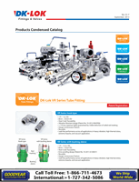
V96 Series
Rising Stem PlugValves
Ordering information and Dimensions
How to order
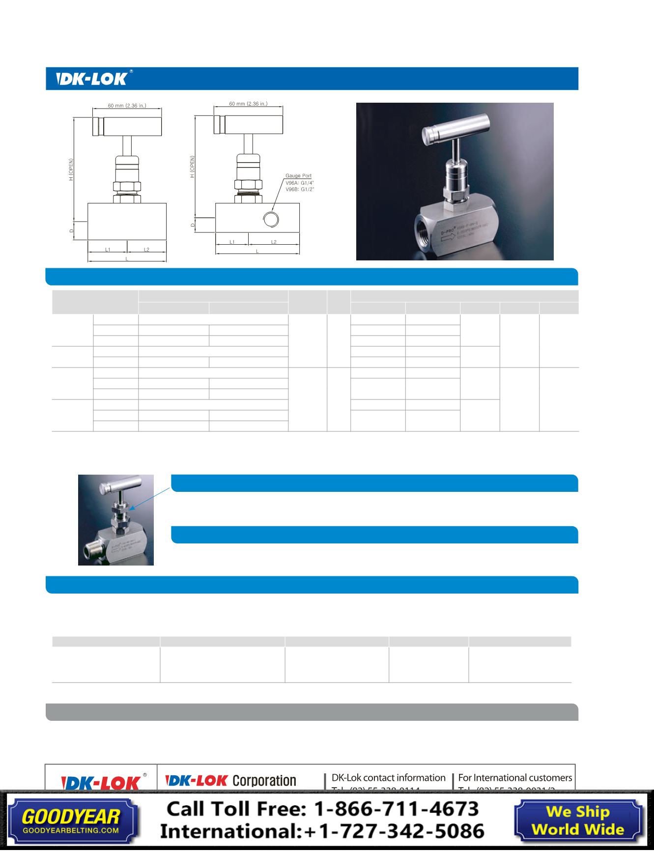
Panel Mounting option
Sour Gas Service option
Safe Valve Selection
Basic Ordering
Number
End Connections
Orifice
mm(in.) Cv
Dimensions, mm(in.)
Inlet
Outlet
L
L1
L2
D
H
V96A-
F-4N
1/4 in. Female NPT
4.8
(0.187) 0.63
56.9 (2.24)
28.4 (1.12)
28.4
(1.12)
12.7
(0.5)
95.8
(3.77)
MF-4N
1/4 in. Male NPT
1/4 in. Female NPT
73.4 (2.90)
45.2 (1.78)
MF-8N4N
1/2 in. Male NPT
1/4 in. Female NPT
76.5 (3.01)
48.0 (1.89)
V96A-G4*- F-4N
1/4 in. Female NPT
72.9 (2.87)
28.4 (1.12)
44.4
(1.75)
MF-8N4N
1/2 in. Male NPT
1/4 in. Female NPT
124 (4.87)
79.2 (3.12)
V96B
F-8N
1/2 in. Female NPT
6.4
(0.25)
1.8
67.6 (2.66)
33.8 (1.33)
33.8
(1.33)
16.0
(0.63)
97.3
(3.83)
MF-8N
1/2 in. Male NPT
1/2 in. Female NPT
88.6(3.49)
54.9 (2.16)
MF-12N8N
3/4 in. Male NPT
1/2 in. Female NPT
V96B-G8*-
F-8N
1/2 in. Female NPT
90.9 (3.58)
33.8 (1.33)
57.2
(2.25)
MF-8N
1/2 in. Male NPT
1/2 in. Female NPT
142 (5.58)
84.6 (3.33)
MF-12N8N
3/4 in. Male NPT
1/2 in. Female NPT
All dimensions shown are for reference only and are subject to change.
• V96A-G4* gauge port: 1/4 in. Female NPT, V96B-G8*: 1/2 in. Female NPT.
• Gauge port valves with pipe insulation extended body of 2.0 in. (50 mm) are listed in
blue
.
Select desired valve basic ordering number, and applicable options from designators listed below.
Example: V96A-F-4N
- PK
-EP
-PM
- SG
- S
Seat Designator
Stem tip O-ring Designator
Panel mounting Designator Sour Gas Designator Body Material Designator
Nil
: Acetal
PK
: PEEK
PA
: Teflon PFA
Nil
: FKM O-ring
EP
: EPDM
KZ
: Kalrez
BC
: Buna C
BN
: Buna N
PM
: Panel Mounting
SG
: Sour Gas
S
: SS316
We reserve the right to change specifications stated in this catalog for our continuing program of improvement.
Panel hole drill size 25/32 in. (19.8 mm), max. panel thickness 1/2 in. (12.7 mm).
To order, add -
PM
as a suffix to the valve ordering number. Example: V96A-F-4N-
PM
Materials are selected in accordance with NACE standards.
To order, add -
SG
as a suffix to the ordering number. Example: V96A-F-4N-
SG
The selection of a valve for any application or system design must be considered to ensure safe performance. Valve function, valve
rating, material compatibility, proper installation, operation and maintenance remain the sole responsibility of the system designer
and the user. DK-Lok accepts no liability for any improper selection, installation, operation or maintenance.