


 166 / 235

Valves
2
© Copyright 2001-2013. All Rights Reserved.
V86, VC86 Series
Ball Valves
Factory Test
2-Way On-off Valves
Cleaning and Packaging
•
2-way positive shut off and 3-way directional control of
fluids in process, power and instrument application.
•
Valves are designed to control fluids in full open or full
closed position.
•
Valves that have not been actuated for a period of time may
have a higher initial actuation torque.
•
Valves must be in open position during system test not to
damage the valve seat.
•
Sour Gas Service NACE MR0175 available.
Every valve is tested with nitrogen gas @1,000 psig (68 bar) for
leakage at the seat to a maximum allowable leak rate
of 0.1 SCCM. The stem packing is tested with nitrogen gas
@1,000 psig for no detectable leakage.
CNG valve ordering number :
The basic ordering number listed in black
are not for CNG/NGV applicable valves.
Every valve is cleaned and packaged in accordance with DK-Lok
cleaning standard DC-01. Special cleaning and packaging in
accordance with DK-Lok DC-11 ensures compliance with product
cleaning of ASTMG93 Level C is available for valves with PCTFE seat.
Operation
Basic
Ordering Number
End Connections
Inlet & Outlet
Orifice
Cv
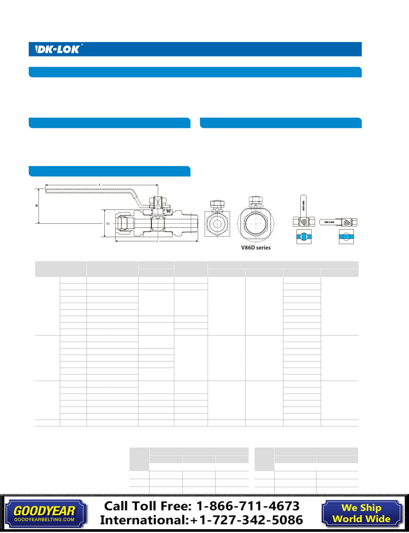
Dimensions mm (
in.
)
mm (
in.
)
A
H
L
SQ
V86A-
VC86A-
D-4T
1/4 in. Dk-Lok
4.8 (
0.19
)
1.2
108.3
(
4.26
)
38.4
(
1.52
)
97.12 (
3.82
)
32.0
(
1.26
)
D-6T
3/8 in. Dk-Lok
7.1 (
0.28
)
3.7
104.5 (
4.11
)
D-8T
1/2 in. Dk-Lok
10.0 (
0.39
)
7.5
109.6 (
4.31
)
F-4N
1/4 in. Female NPT
74.0 (
2.91
)
F-6N
3/8 in. Female NPT
77.0 (
3.03
)
F-8N
1/2 in. Female NPT
85.0 (
3.35
)
M-4N
1/4 in. Male NPT
7.1 (
0.28
)
3.7
95.4 (
3.76
)
M-6N
3/8 in. Male NPT
10.0 (
0.39
)
7.2
95.4 (
3.76
)
M-8N
1/2 in. Male NPT
7.5
100.2 (
3.94
)
V86B-
VC86B-
F-8N
1/2 in. Female NPT
12.7 (
0.50
)
10.1
149.0
(
5.86
)
50.8
(
2.0
)
89.0 (
3.50
)
40.0
(
1.57
)
F-12N
3/4 in. Female NPT
90.0 (
3.54
)
D-12M
12mm DK-Lok
10.0 (
0.39
)
112.6 (
4.43
)
D-16M
16mm DK-Lok
12.7 (
0.50
)
115.0 (
4.53
)
D-8T
1/2 in. DK-Lok
10.4 (
0.41
)
114.6 (
4.51
)
D-10T
5/8 in. DK-Lok
12.7 (
0.50
)
114.4 (
4.5
)
D-12T
3/4 in. DK-Lok
114.8 (
4.52
)
V86C-
VC86C-
F-12N
3/4 in. Female NPT
19.0 (
0.75
)
30.0
149.0
(
5.86
)
56.0
(
2.2
)
96.0 (
3.78
)
50.0
(
1.97
)
F-16N
1 in. Female NPT
111.0 (
4.37
)
D-12T
3/4 in. DK-Lok
15.7 (
0.62
)
19.0
125.0 (
4.92
)
D-16T
1 in. DK-Lok
19.0 (
0.75
)
30.0
134.0 (
5.27
)
M-12N 3/4 in. Male NPT
15.7 (
0.62
)
19.0
119.0 (
4.68
)
M-16N
1 in. Male NPT
19.0 (
0.75
)
30.0
129.0 (
5.07
)
VC86D-
F -16N
1 in. Female NPT
25.0 (
0.98
)
Full Bore
193.7 (
7.62
)
84.1 (
3.31
)
112.90 (
4.44
)
70 (
2.76
)
Standard Valves
Valve
Series
System Pressures, bar (psig)
0 (0)
344 (5000)
Torque
Unit: Nm
VC86B
5.19
10.59
VC86C
2.15
5.88
VC86D
7.35
9.80
CNG/NGV Valves
Valve
Series
System Pressures, bar (psig)
0 (0)
334 (5000)
413 (6000)
Torque
Unit: Nm
V86A
3.92 (2.89)
-
6.37 (4.69)
V86B 7.35 (5.42)
10.30 (7.59)
-
V86C 12.26 (9.04) 19.61 (14.46)
-
Table 3.
2-Way Valve Actuation Torque
Ordering Information and Dimensions