


 22 / 60

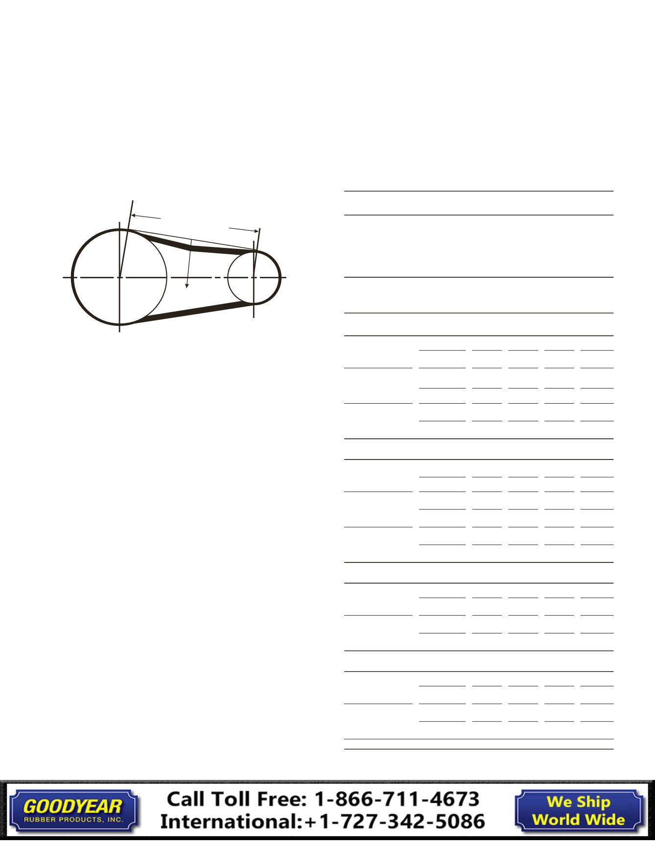
Table 10 Belt Deflection Force
Belt Deflection (force pounds)
Uncogged
HY-T® Belts
and Uncogged
HY-T® Torque
Team®
Cogged
Torque-Flex®
and Machined
Edge Torque
Team® Belts
Smallest Sheave
Diameter Range
RPM Range
Used
Belt
New
Belt
Used
Belt
New
Belt
A, AX Cross Section
3.0-3.6
1000-2500 3.7
5.5
4.1
6.1
2501-4000 2.8
4.2
3.4
5.0
3.8-4.8
1000-2500 4.5
6.8
5.0
7.4
2501-4000 3.8
5.7
4.3
6.4
5.0-7.0
1000-2500 5.4
8.0
5.7
9.4
2501-4000 4.7
7.0
5.1
7.6
B, BX Cross Section
3.4-4.2
860-2500
4.9
7.2
2501-4000
4.2
6.2
4.4-5.6
860-2500 5.3
7.9
7.1
10.5
2501-4000 4.5
6.7
6.2
9.1
5.8-8.6
860-2500 6.3
9.4
8.5
12.6
2501-4000 5.5
8.2
7.3
10.9
C, CX Cross Section
7.0-9.0
500-1740 11.5 17.0 14.7 21.8
1741-3000 9.4
13.8 11.9 17.5
9.5-16.0
500-1740 14.1 21.0 15.9 23.5
1741-3000 12.5 18.5 14.6 21.6
D Cross Section
12.0-16.0
200-850 24.9 37.0
851-1500 21.2 31.3
18.0-20.0
200-850 30.4 45.2
851-1500 25.6 38.0
Mark the center of the span. At the center mark, use a
tension tester and apply a force perpendicular to the span
large enough to deflect the belt 1/64 inch for every inch of
span length (example: a 100 inch span requires a deflection of
100/64 inch or 1_⁄{| inches).
Compare the actual deflection force with the values in
Tables 10 and 11 (at right and page 23).
A force below the target value indicates under-tension. A force
above the target indicates over-tension.
Force
Span Length
Deflection 1/6
4 in. per in. of span
Measuring the Span Length
22
Banded Belts
Installation Guide