


 158 / 235

V824 / V825 Series
Ball Valves
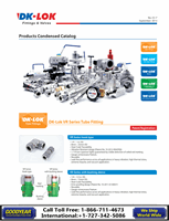
V824
Crossover 4-way Ball Valves
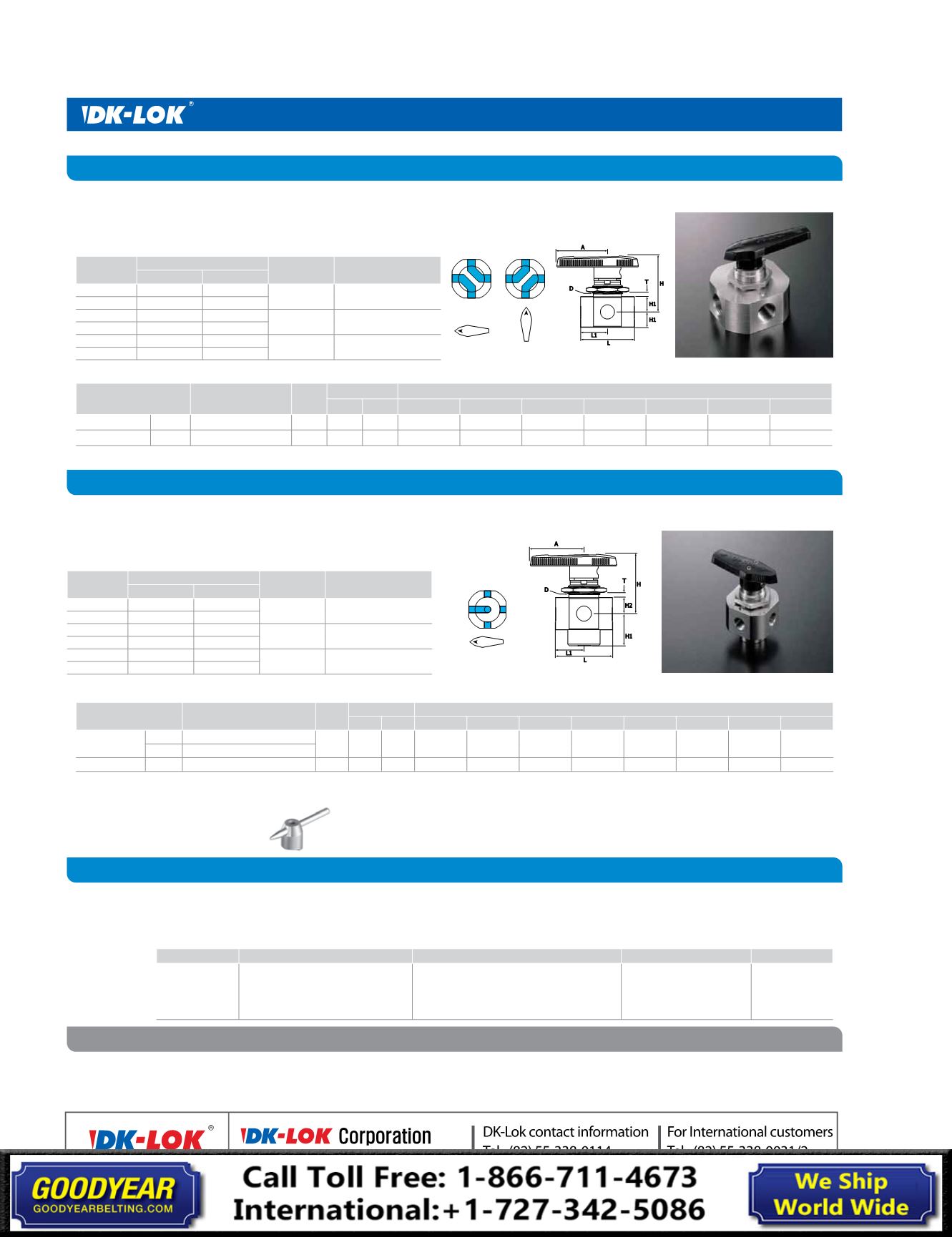
V825
Switching 5-way Ball Valves
Ordering Information and Table of Dimensions
How to Order
Safe Valve Selection
Ordering Number End Connection Cv Orifice
Dimensions, mm(in.)
mm inch L
L1
H1
A
T*
D
H
V(L, G)824A- F2N-S 1/8 in. Female NPT 0.08 1.6 0.062
39.4 (
1.55
)
19.8 (
0.78
)
11.2 (
0.44
)
38.9 (
1.53
)
4.8 (
3/16
) 23.1 (
29/32
) 42.7 (
1.68
)
V(L, G)824B- F8N-S 1/2 in. Female NPT 1.6 7.1 0.281
79.5 (
3.13
)
39.6 (
1.56
)
17.5 (
0.69
)
76.2 (
3.00
)
9.7 (
3/8
)
38.1 (
1 1/2
) 61.7 (
2.43
)
T* indicates maximum panel thickness
D
: Panel Hole
Select applicable valve pattern, options and body material from designators listed below.
The selection of a valve for any application or system design must be considered to ensure safe performance. Valve function, valve
rating, material compatibility, proper installation, operation and maintenance remain the sole responsibillty of the system designer
and the user. DK-Lok accepts no liability for any improper selection, installation, operation or maintenance.
V824A-F2N
V82B-D4T
VG82A-D2T
-A
-NL
-AH
-B
-S
2-way
Botton mounting
Valve with no lubricant
Bar handle
Body material
A
: 2-way angle
pattern
TM
: Botton mounting
Note
: Botton mounting option is
applicable only to the in-line
pattern 2-way valves.
NL
: No lubricantValve
Note
:Valve with no lubricant is factory tested at
200 psig (13 bar).
This valve pressure rating is 200 psig (13 bar).
Nil
: Standard Nylon handle
AH
: Aluminum bar handle
BH
: Stainless bar handle
S
: SS316
B
: Brass
Ordering Number
End Connection Cv Orifice
Dimensions, mm(in.)
mm inch L
L1
H1
H2
A
T*
D
H
V(L, G)825A- F2N-S
1/8 in. Female NPT
0.07 1.6 0.062
39.4 (
1.94
)
19.8 (
0.78
)
22.4 (
0.88
)
38.9 (
1.53
)
38.9 (
1.53
)
4.1 (
5/32
)
23.1 (
29/32
)
42.9 (
1.69
)
F2G-S
1/8 in. ISO Parallel Threads
V(L, G)825B- F8N-S
1/2 in. Female NPT
3.5 10.3 0.406
79.5 (
3.13
)
39.6 (
1.56
)
17.5 (
0.69
)
76.2 (
3.00
)
76.2 (
3.00
)
9.7 (
3/8
)
38.1 (
1 1/2
)
61.7 (
2.43
)
T* indicates the maximum panel thickness. 3.2 mm (1/8 in.) minimum panel thickness.
D
: Panel Hole
Handle Options
Aluminum Bar
Stainless Bar
Add-AH to the valve ordering number.
Add-BH to the valve ordering number.
Example:V824A-F-2N-AH-S
Example:V824A-F-2N-BH-S
Features
• Crossover of two streams
• Mechanical stop ensures positive port positioning
Technical Data with standard PTFE, PFA and integrated PFA seat
Valve
Series
Pressure Rating
SEAT
material
Temperature
Range
psig
bar
V824A
2500
172
PTFE
10°C to 65°C
50°F to 150°F
V824B
1500
103
VL824A
2500
172
PFA
-54°C to 65°C
-65°F to 150 °F
VL824B
1500
103
VG824A
2500
172
"Integrated
PFA"
-54°C to 150°C
-65°F to 302°F
VG824B
1500
103
Features
• Flow switches from a single port to multiple ports or from multiple ports to a single port.
• Spring-loaded detent ensures exact port positioning.
Technical Data with standard PTFE, PFA and integrated PFA seat
Valve
Series
Pressure Rating
SEAT
material
Temperature
Range
psig
bar
V825A
2500
172
PTFE
10°C to 65°C
50°F to 150°F
V825B
1500
103
VL825A
2500
172
PFA
-54°C to 65°C
-65°F to 150 °F
VL825B
1500
103
VG825A
2500
172
Integrated
PFA
-54°C to 150°C
-65°F to 302°F
VG825B
1500
103
Ordering Information and Table of Dimensions