


 55 / 114

SECTION
V-GUIDES / VANNER / FLANGED EDGES
FABRICA
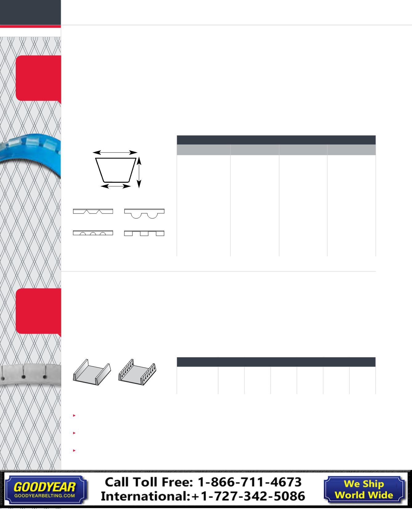
V-GUIDES
V-guides are used to help belts track properly on conveyors. Used on the bottom of a belt they
serve as a guide, but can also be attached to the top of the belt and used as a vanner edge.
A broad range of V-guide profiles are available. Single center guides are popular for narrow belts.
Wider belts many times use a V-guide on the bottom of each belt edge and are popular for short
and reversing conveyors.
VANNER / FLANGED EDGES
The primary purpose of vanner edges is to prevent material from spilling off the outside edges
of the conveyor belt. Flanges are offered in rubber, which are hot vulcanized to the top cover, or
in PVC, which are “hot welded” to the top surface.
F A B R I C A T I O N S - W E
V-guides can be attached to any belt. We stock the industry standards in addition to a variety of European
sizes. Guides may be utilized for tracking purposes, cleats and side flanges.
Size
X
Y
Z
0
3/8”
1/4”
1/4”
.375”
.25”
.25”
A
1/2”
5/16 ”
5/16 ”
.5”
.3125”
.3125”
B
5/8”
3/8”
3/8”
.625”
.375”
.375”
C
7/8”
9/16 ”
1/2”
.875”
.5625”
.5”
V-GUIDE, V-GUIDE CLEATS OR EDGE FLANGES
X
Z
Y
V-GUIDES
SAMPLE CLEAT DIMENSIO
SCOOP CLEAT
T-CLEATS
For those steep inclines where a strong and reliable cleat is required.
Our cleating process insures that the cleat stays on.
Standard cleat sizes 1/2” – 4”
NOTE:
For best results, a
pulleyʼs V-guide groove
should be 1/16” greater
than the guide on each
side and the bottom.
Size
Height
Foot Base
Thkness
1/2”
.5”
1.00
0.375
1”
1.0”
1.50
.0375
1 1/2”
1.5”
1.50
.0375
2”
2.0”
1.50
0.375
2” beefy
2.0”
1.50
0.500
3”
3.0”
1.50
0.375
3” beefy
3.0”
1.50
0.500
4”
4.0”
1.50
0.500
2” scoop
2.0”
1.75
3” scoop
3.0”
1.75
TL25mm
.984”
TL30mm
1.181”
TL40mm
1.575”
TL50mm
1.969”
IG 1 1/2” 1.5”
IG 2”
2.0”
V-notched
U-notched
Mill Apron
Fully Segmented
V-GUIDE GENERAL SPECS
TYPE
X
Y
Z
K-6
6 mm
4.5 mm
3.5 mm
Modified K-8
6 mm
4.5 mm
3.175 mm
K-8
8 mm
4.5 mm
4.5 mm
K-10/O
3/8"
10 mm 1/4"
6 mm 1/4"
6 mm
Modified A
7/16"
11.112 mm 3/8"
9 mm 1/4"
6 mm
K-13/A
1/2"
13 mm 5/16"
7 mm 5/16"
7.5 mm
K-17/B
5/8"
17 mm 3/8"
9 mm 3/8"
11 mm
K-22/C
7/8"
22 mm 9/16"
12 mm 1/2"
11 mm
D
1-1/4"
32 mm 3/4"
19 mm 3/4"
19 mm
E
1-3/8"
35 mm 1"
25.4 mm 3/4"
19 mm
Mill Apron
3-1/8"
79 mm 2-1/4"
57 mm 7/8"
22 mm
Vanner edges are popular in “weigh feeder” applications, where product is weighed or metered as it feeds
another system.
Vanner edges are furnished in solid form, or siped/slit from the top to the bottom of the vanner, where a hole
is drilled to help with flexibility and to prevent the slit section from splitting or tearing.
This process is referred to as drilling and siping, which improv s the flexibility of the vanner and allows it
to operate on smaller pulley diameters. For rubber compounds, flanges come in a standard hardness of
60 durometer, but they are available in a softer 40 durometer compound for wrapping smaller pulleys.
COMPOUNDS:
SBR/GR II, Oil-Resistant, Heat-Resistant, Black PVC, White PVC
VANNER EDGE
Cleat Height
1/2"
1"
1-1/2"
2"
2-1/2"
3"
Solid
9"
10"
16"
18"
20"
24"
Drilled/Siped
6"
6"
8"
12"
12"
16"
Solid
Drilled and Siped
FLANGED
DRILLED
AND SIPED
When additional
flexibility is
needed to flex
around a pulley,
vanner edges
can be drilled
and siped.
V-guides
can also be
HF Welded.
See p. 60
LIGHTWEIGHT
& HEAVY-DUTY
LIGHTWEIGHT
& HEAVY-DUTY