Page 259 - 4300 Catalog Cover.pdf
SEO Version


M5
Parker Hannifin Corporation
Tube Fittings Division
Columbus, Ohio
4300 Catalog
Hydraulic Flanges and Components
Dimensions and pressures for reference only, subject to change.
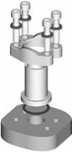
Fig. M3 – Four-Bolt Flange Connection (SAE J518)
Code 61/62 Clamp
Tube or Hose End
Flange Head
O-Ring
Clamping Bolt
How Flange Connections Work
The four-bolt flange connection (SAE J518) is a proven leak-free
connection, especially suited for larger sizes. As a result, it has
achieved worldwide acceptance.
The connection’s success is in its simplicity. It is a static face
seal using a high durometer O-ring for the seal and clamps
and bolts for holding power as shown in Fig. M3. Alternatively,
a bonded seal plate is between the port face and the flat face of
a mechanically formed (flanged with Parflange
®
process) tube
as shown
achieve the same results.
The (O-ring) seal is compressed between the bottom of the
groove in the flange head and the flat surface of the port or
flange pad, providing a reliable soft seal.The alternate seal plate
has a high durometer bonded rubber seal on the inside edge,
which compresses between the two flat surfaces, providing a
soft seal with the same reliability. A metal-to-metal contact at
the outer face of the flange with the port face keeps the seal
from extruding under pressure. This metal-to-metal contact is
maintained by the clamping force provided by tightening the
bolts via the clamps.
This simple design provides several advantages over threaded
port connections, such as NPTF, SAE, BSPP, ISO 6149, etc.,
in larger sizes:
• Ability to connect up to 5 inch O.D tube (Code 61
only)
• Much lower tightening torque required from the four
bolts compared to that required for equivalent size
threaded port
• Less tightening torque means smaller wrenches and
wrench swing clearances — providing ease of as-
sembly in tight quarters
• Up to 6000 psi capability through 2” size (Code 62
only)
• Single seal point between tube/pipe/hose assembly
and the port
• Ease of disassembly through use of split clamps
The connection has one disadvantage — it requires a larger
area (foot print) on the component than an equivalent threaded
port.
Assembly and Installation
Please refer
r theassemblyand installation instruc-
tions for Hydraulic Flanges and Components fittings.
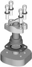
Fig. M4 – Formed Tube with ISO 6162 (SAE J518) Connection
Parflange Sleeve
Code 61/62 Clamp
Seal Plate
Tube
Feature
Advantage
Benefit
Conform to SAE J518 and
ISO 6162
Controls dimensions and tolerances of code 61 and
62 port connections
Insures interchangeability and consistency
Forged Construction
Reliable, long life performance
No downtime, reduced costs
Compact envelope size, no sharp edges
Reduced weight
Over 60 Configurations
Flexibility in plumbing, match system needs
Best solution and best value
Parflange Technology
Designed to be used with Code 61/62 fittings
Eliminates messy and time consuming brazing
process
Mounting Hardware
Grade 8 bolts standard
Performs in rigorous applications for the life of the
flange
Flange Kits
Flange with hardware for mounting (o-ring, bolts and
lockwashers)
Reduces order and assembly error
Powered by FlippingBook Publisher