Page 258 - 4300 Catalog Cover.pdf
SEO Version


M4
Parker Hannifin Corporation
Tube Fittings Division
Columbus, Ohio
4300 Catalog
Hydraulic Flanges and Components
Introduction
The 4-bolt flange connections conforming to SAE J518 and ISO
6162-1 and -2 are proven, leak-free connections, especially
suited for larger sizes, higher pressures and assembly in tight
quarters. Threaded port connections such as SAE straight
thread O-ring and ISO 6149 are reasonably easy to assemble
and provide 6000 psi and higher pressure capability up to size
12 (M27).Beyond this size the pressure rating starts to decrease
and assembly torques increase rapidly. The 4-bolt flange port
connections provide ability to connect larger sizes and achieve
higher-pressure capability at reasonable assembly torques. Be-
cause of the lower assembly torques compared to an equivalent
size threaded port, these connections are well suited for tight
quarters where wrench clearances are limited. Parker 4-bolt
flange products described in this part of the catalog provide
various means of connecting tubes, hoses, pipes and threaded
fittings to 4-bolt flange ports. The discussion below provides an
overview of some of the available flange products.
Design and Construction
Parker 4-bolt flange products are designed to provide different
methods of connecting a tube, hose, pipe or another fitting to
the SAE standard 4-bolt flange port.
Flange Fittings
— All Parker flange fittings, except for those
with square mounting hole patterns (nomenclature code QS),
are designed to conform to O-ring groove, bolt holes and bolt
pattern dimensions of either Code 61 or Code 62 of SAE J518
and ISO 6162-1 (Code 61) or -2 (Code 62).
The flange adapters (Code Q1 and Q2), and flange block fittings
(Codes Q1B, Q2B and QSB) have O-ring grooves conforming
to dimensions in SAE J518. The flange block fittings (Codes
Q1B and Q2B) have through holes for the mounting bolts, again
conforming to SAE J518. There is no industry standard for the
bolt pattern of the square pattern block flanges with codes QSP
and QSB.
The flange pad fittings (Codes Q1P, Q2P, and QSP) have a flat
face (no O-ring groove) and the mounting holes are tapped.
Where these fittings are used, the seal is in the mating part
(flange adapter, flange hose fitting, flange block fitting, etc.) as
shown in Fig. M1.
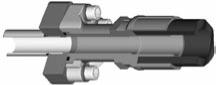
Fig. M2 – Assembly / Removal SAE J518 Connection
Parflange Sleeve
Code 61/62 Clamp
Seal Plate
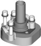
Fig. M1 – Flange Pad Fitting
Flange Pad
Fitting
Flanged Hose Fitting
O-ring Seal in Hose Fitting
Flange Clamps
— Clamps are used for providing the holding
power to the 4-bolt flange connection. They are offered in split
and captive (one-piece) versions.The captive version is also of-
fered with either drilled or tapped bolt holes. The captive flange
clamp with tapped holes is used while connecting a tube to
another tube or a hose.
Parker flangeclampsare forged for higher strengthanddurability.
They meet all requirements of SAE J518.The split clamps make
it easy to assemble the connection in close quarters. They also
make removal of the flange head component, such as a hose
assembly, easy by loosening all four bolts and removing one
clamp half, as shown in Fig. M2.
Junction Block Tees
— These are solid block union fittings to
connect two tube/hose assemblies using 4-bolt flange connec-
tion, at a junction, to SAE 4-bolt flange port, or three tube/hose
assemblies to each other.
Connector Plate
— Connector plate is used as a middle plate
to connect two flange heads with O-ring grooves, such as two
hose assemblies with flange connection ends. The flat surface
of the plate provides sealing surface on each side for the O-ring
housed in the hose ends.
Spacer Plate
— Spacer plate provides access to the system
fluid via the gage port on the side. The plate is between the
flange connection to provide this access.
Plugs
— Plugs provide a means to block off the 4-bolt flange
port with and without clamps, and to plug the end of a pipe (via
welding).
TankWeld Adapter
—Tank weld adapters provide a means of
flange connection to a fabricated reservoir or tank.
Dimensions other than the O-ring groove, bolt holes, bolt pat-
tern, and the flange foot print (for codes Q1B and Q2B only)
are not governed by any industry standard. However, Parker
product design follows common industry practice and sound
engineering.
Table M1 – Standard Material Specifications for Hydraulic
Flanges and Components
Note:
Split flange clamps are zinc clear (or Cr6 free) chromate. All
other steel flanges are oil dipped.
Hydraulic Flanges
Steel
Stainless Steel
ASTM Type ASTM Type
4-Bolt Flanges
A108 C1020 A240
316L
Flange Clamps
A108 C1045
A351 /
A743
Nitronic
50
HHCS Bolts
SAE Grade 8
—
—
SHCS Bolts
— — A240
316
Powered by FlippingBook Publisher