


 9 / 172

Brass Valves and Wyes
7
Dixon Fire 2016
877.712.6179 •
dixonvalve.comA
Brass
Valves &
Wyes
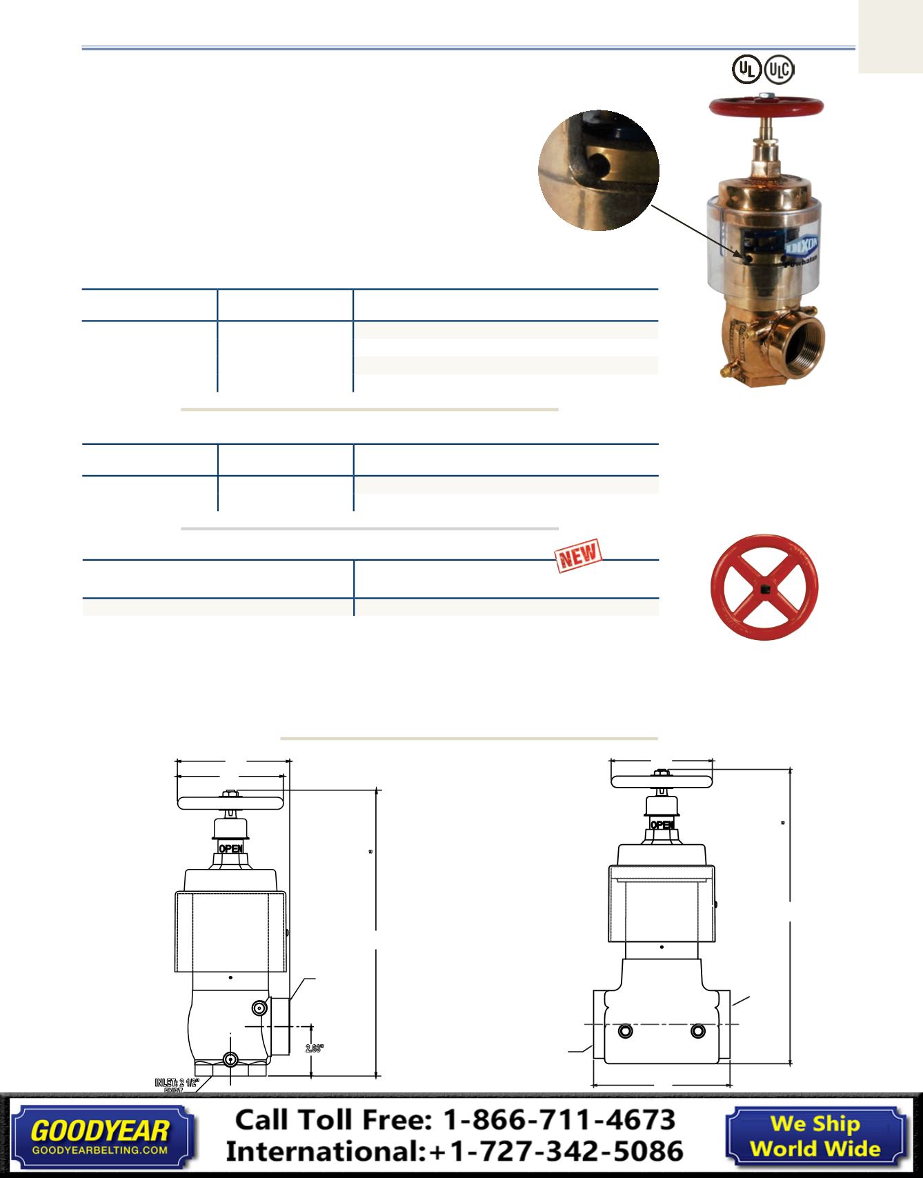
uses ⅜" rod:
<30 ft lbs required to adjust
Field Adjustable Pressure Reducing Valves
Features:
•
U/L listed
•
allows flexibility during installation with the ability to adjust
settings once installed as hydraulic conditions change
•
used in applications where the inlet pressure is greater than
175 PSI
•
¼" NPT gauge ports - both sides, drilled and tapped
standard
•
⅜" adjusting rod included
•
available tamper switch (
42-019-01587
), consult Dixon™
6.10"
5.75"
2.68"
15.52"
INLET: 2 1/2"
FNPT
OUTLET: 2 1/2"
FNPT
OR
MALE THREAD
PER ORDER
*Valve height
closed: 14.88
"
add 1" to height
for groove body
7.75"
5.75"
16.86"
INLET: 2 1/2"
FNPT
OUTLET: 2 1/2"
FNPT
*Valve height
closed: 16.22
"
add 2" to width for groove body
Setting Instructions:
1. Determine desired outlet pressure for known inlet pressure.
2. Remove the tamper-resistant screw and slide the plastic cover up to access the adjusting nut.
3. Use a ⅜" diameter rod in any one of the 6 holes in the adjusting nut and rotate counter
clockwise to increase the pressure at the outlet.
4. Check valve under pressure under static and under the anticipated flowing conditions to
ascertain that the setting produces the expected results.
Dimensions
angle valves
1
Inlet
Outlet
Cast Brass
Part #
2½" FNPT
2½" MNST
FAPRAV250F
2½" FNPT
2½" FNPT
FAPRAVF250
2½" groove
2½" MNST
FAPRAVG250F
2½" groove
2½" groove
FAPRAVG250G
straight valves
2
Inlet
Outlet
Cast Brass
Part #
2½" groove
2½" groove
FAPRVG250
2½" FNPT
2½" FNPT
FAPRVF250
angle valve
1
straight valve
2
Replacement Parts
Description
Cast Iron
Part #
handwheel
46-030-00025