


 18 / 60

18
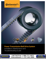
Laser Alignment Tool
With our Laser Alignment Tool, you can quickly align drive
components to improve efficiency and reduce costly
maintenance. Much easier to use than a straight edge, it
attaches in seconds and when the highly-visible sight line lies
within the target openings, the pulley/sprockets are aligned.
10. Identify correct belt
Always select belts to match sheave grooves. Use a sheave
groove gauge to determine the proper belt cross section
(Figure A). Make sure that the space between the grooves in
the sheaves matches the spacing between belt ribs. Do not
use Torque Team® belts in deep groove sheaves; such sheaves
could cut through the backing that holds the ribs together.
Use a belt gauge to verify the old belt cross section when belt
identification is no longer legible (Figure B).
8. How to remove a sheave made with a
taper-lock hub
Remove all the setscrews.
Place two of the setscrews in the holes that are threaded in the
bushing only.
Turn the setscrews alternately and evenly. This movement will
unlock the grip and permit easy removal of the assembly with
no shock to the bearings or machinery.
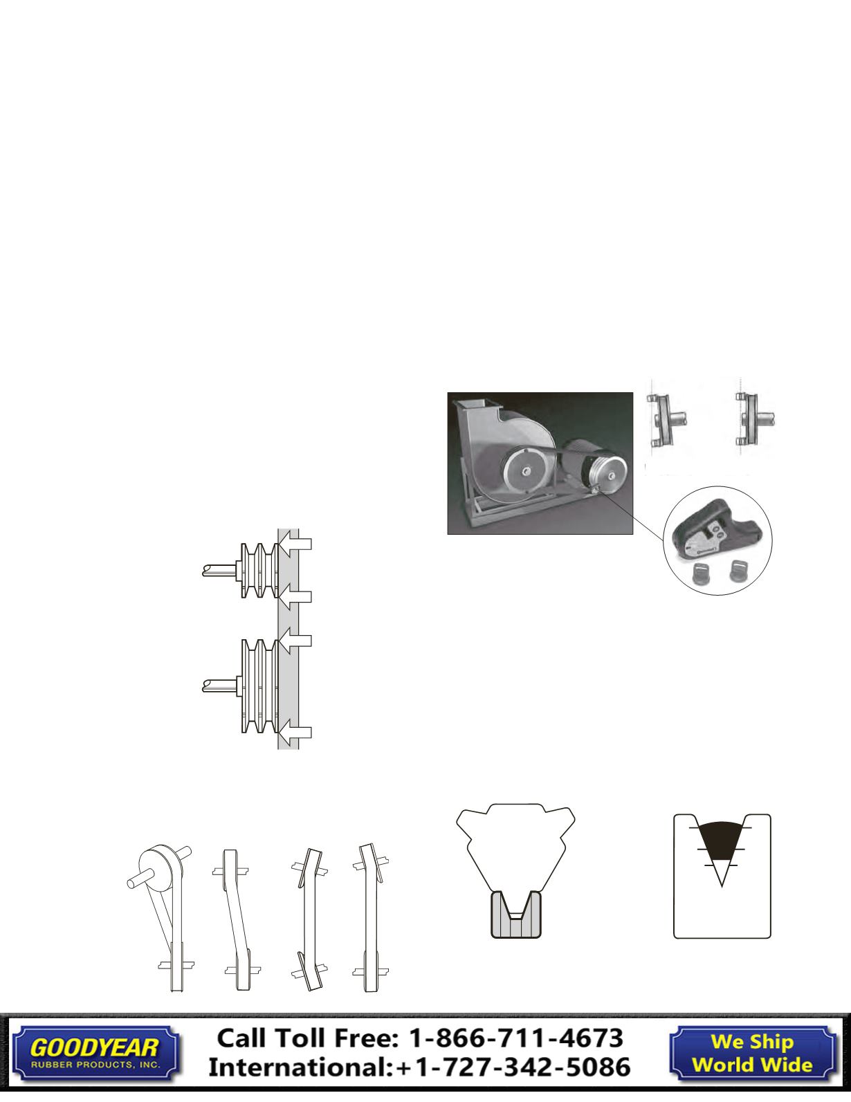
9. Check alignment
Proper alignment is essential for long Torque Team®
V-belt life. Check belt alignment whenever you maintain or
replace belts or whenever you remove or install sheaves. Limit
misalignment to 1/2 degree or approximately 1/10 inch per
foot of center distance.
The illustration above shows the correct way to check
alignment between two sheaves with a straight edge. Check
both front and back alignment. Straight edge should touch
sheaves at the four points indicated.
Non-parallel shafts or sheaves not aligned axially can cause
angular misalignment.
Misaligned
Aligned
8V
Over 22.4
O.D.
42°
Up to 16.00
O.D.
38°
16.00 Thru 22.4
O.D.
40°
Figure A
8V
5V
3V
1in.
5/8 in.
3/8 in.
Figure B
Banded Belts
Installation Guide