


 553 / 961

Valves
I
556
DPL418
877.963.4966 •
dixonvalve.comI
Safety Check Valves for Pneumatic Applications
Safety Check Valves
Application:
•
used in temporary plant/factory air lines, construction sites, shipyards or utilities
•
not for use in applications where 100% of the available air is required, i.e. sand blast,
pile driving rigs,expansion joint blow down pipes, etc.
Features:
•
high flow valve provides optimum performance
•
controls excess air flow (SCFM) in only one direction
•
automatically senses change in air flow and shuts off the flow in the event of a surge in
excess of valve flow rating thus preventing hose whip
•
solid brass body and valve
•
stainless steel spring and roll pin
•
maximum operating pressure:
350 PSI
•
maximum temperature:
250°F (121°C)
•
does not prevent backflow
Specification:
•
conforms to OSHA regulation 1926.302 (b) (7) requiring a safety device at the source of the
air supply and at branch air lines
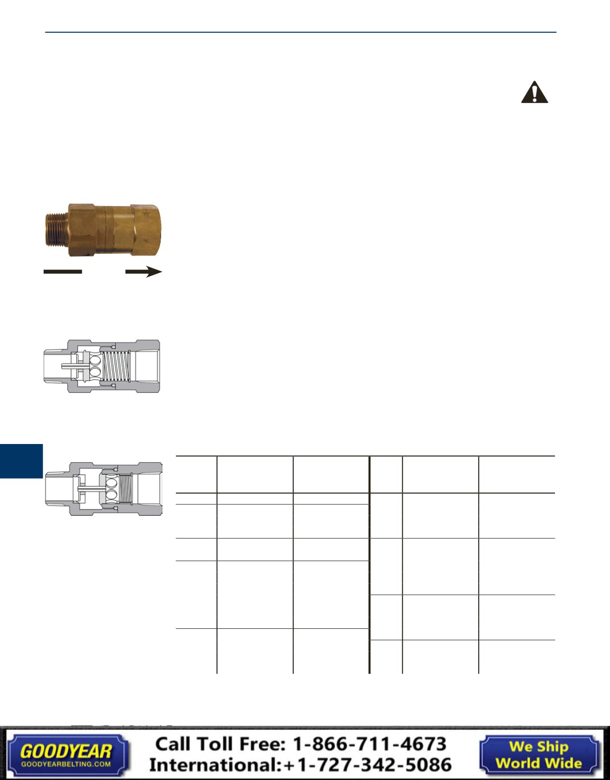
How It Works:
•
Safety check valves utilize the pressure differential across the valve to operate the valve and
spring assembly. The pressure differential is directly related to the flow of air (SCFM) through
the valve.
•
When the pressure differential is within the operating limits - below the cutoff flow - of the
unit, the force on the valve exerted by the spring is greater than that caused by the pressure
differential (see "Open Position" graphic above). The valve remains open and normal
operation continues.
•
When the pressure differential is above the cutoff limit, the force on the valve exerted by the
pressure differential is greater than the force exerted by the spring, and the valve closes (see
the "Closed Position" graphic above).
•
After the repair is made, normal operation is automatically enabled when pressure across the
valve equalizes through the bleeder hole.
•
The valve spring size can be specified by determining the air flow during normal operation
and by estimating the air flow if a failure or rupture occurs.
NPT &
Hose
ID Size
Cut-off Flow Rate
(SCFM at 90 PSI)
Brass
Part #
NPT &
Hose
ID Size
Cut-off Flow Rate
(SCFM at 90 PSI)
Brass
Part #
¼"
23-29
SCVL2
1¼"
260-290
SCVL10
⅜"
30-36
SCVL3
300-340
SCVM10
39-47
SCVM3
440-500
SCVS10
52-65
SCVS3
570-630
SCVH10
½"
70-78
SCVM4
1½"
300-360
SCVL12
80-96
SCVS4
470-530
SCVM12
¾"
72-88
SCVL6
564-602
SCVX12
92-108
SCVM6
640-720
SCVS12
112-128
SCVR6
750-830
SCVH12
132-148
SCVJ6
2"
510-590
SCVL16
160-180
SCVS6
725-825
SCVM16
180-200
SCVH6
900-1050
SCVS16
1"
165-195
SCVL8
1100-1200
SCVH16
220-260
SCVM8
3"
1200-1400
SCVL24
280-320
SCVS8
2400-2700
SCVS24
310-340
SCVH8
2850-3050
SCVH24
Flow
Direction
Closed Position
Open Position