


 121 / 972

D-5
Cam & Groove
DPL417
877.963.4966 •
dixonvalve.comD
Size represents the coupler or adapter and hose or pipe end (i.e. 200 = 2"). If the coupling is a reducing size, the coupler or
adapter is the first size (i.e. 4030-C is 4" coupler to 3" hose shank).
Ordering System
size
material
style
RB200EZ
200 - A - AL
1. To make connection, slide the adapter into the coupler and with normal hand pressure, press the cam levers down.
2. Uncoupling is as quick and simple as coupling. Just lift the cam arms and remove the adapter.
Operation of Cam and Groove
Specifications on Dixon Cam and Groove
Specifications:
•
Dixon
®
, Boss-Lock™ and EZ Boss-Lock™ cam & groove couplers and adapters are produced to interchange with all product
produced to Commercial Item Description A-A-59326D.
•
No standard exists for the ½" and 8" fittings, and generally these sizes do not interchange with other manufacturers.
•
Dust caps and dust plugs are
not
to be used in pressure applications for safety and environmental reasons.
•
Designed for use with liquids
, consult Dixon
®
for specific recommendations.
Pressure Ratings:
Recommendations based on the use of mating Dixon
®
fittings at ambient temperature
70°F (21°C)
with standard
Buna-N seal installed. For use at elevated temperature or other unusual operating conditions, consult Dixon
®
. Dixon
®
,
Boss-Lock™ and EZ Boss-Lock™ couplers and adapters maximum working pressure are as follows:
Size
½"
¾" thru 2"
2½"
3"
4"
5" and 6"
8"
PSI
150
250
150
125
100
75
50
PSI
(working pressure with King Crimp™ ferrule system)
150
250
150
150
150
75
50
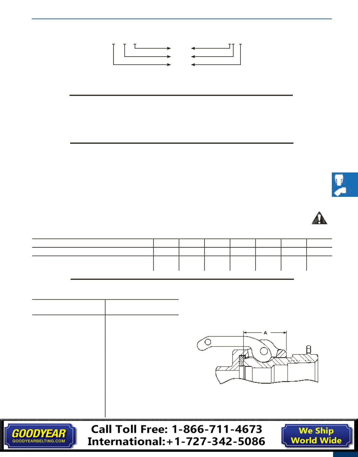
Cam and Groove Nominal Take-Up Lengths
Coupling Size
Dimension A
½"
0.97"
¾"
0.97"
1"
1.20"
1¼"
1.44"
1½"
1.50"
2"
1.81"
2½"
1.82"
3"
1.78"
4"
1.84"
5"
2.00"
6"
2.13"
8"
2.06"
8"
3.22"
Cam and Groove Information