


 201 / 292

199
Dixon Sanitary 2016
800.789.1718
Ball Valves
T
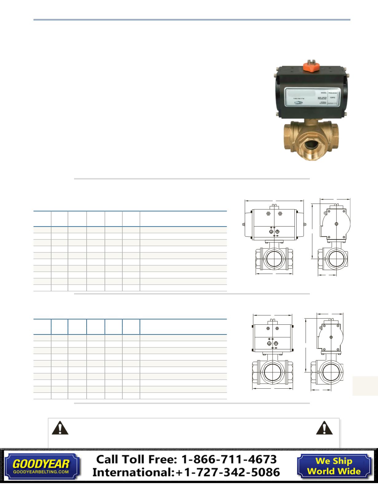
Pneumatically Actuated 3-Way Brass Ball Valves - 'T / L' Port
Spring Return (normally closed)
Double Acting
A wide variety of switches, solenoids, positioners, etc., are available.
Contact Dixon Sanitary at 800.789.1718 or visit
dixonvalve.comfor details.
E
D
C
B
A
E
C
D
A
B
Features:
3-Way Brass Ball Valve
•
reduced port
•
blow-out proof stem
•
chrome-plated brass ball
•
PTFE seats with O-ring backing for low operating
torque
•
ISO 5211 mounting pad
•
100% tested
•
pressure rating:
400 PSI
WOG
100 PSI
WSP
•
maximum temperature:
300ºF
Rack and Pinion Actuator
•
hard anodized aluminum body
•
nickel plated anti-blowout pinion
•
Buna-N O-rings
•
NAMUR mounting
•
bi-directional stops for ±5º travel adjustment
•
80 PSI plant air required
•
visual position indication
•
maximum operating pressure:
120 PSI
•
operating temperature range:
-40ºF
to
200ºF
•
tested to one million cycles
Caution !
Even though there are torque safety factors built into our automated ball valve packages, actual service conditions
must also be considered when selecting the proper product for the appropriate application.
For example:
Severe service conditions such as dirty water, dirty air, all slurries, raw sewage water, oils, and other
viscous fluids can have a dramatic affect in raising the torque requirements of ball valves as much as 75% and therefore larger actuators
may be required. Please consult Dixon when dealing with these types of applications.
*
T
= t-style
*
L
= l-style
All dimensions are given in inches, unless noted. Dimensions
are approximate. Engineering dimensions are available upon
request. Specifications are subject to change without notice.
Size A B C D E
Brass
Part #
¼
" 4.72 2.80 2.64 5.49 1.32
BV3BV*R-0251BBC
⅜" 4.72 2.80 2.64 5.49 1.32
BV3BV*R-0381BBC
½
" 4.72 2.80 2.87 5.49 1.44
BV3BV*R-0501BBC
¾
" 4.81 2.80 3.19 5.49 1.60
BV3BV*R-0751BBC
1" 6.28 3.74 3.74 7.45 1.87
BV3BV*R-1001BBC
1¼" 6.50 3.74 4.39 7.45 2.20
BV3BV*R-1251BBC
1½" 6.99 3.74 4.86 7.45 2.43
BV3BV*R-1501BBC
2" 8.45 4.69 5.73 9.10 2.87
BV3BV*R-2001BBC
2½" 8.90 4.69 6.93 9.10 3.47
BV3BV*R-2501BBC
3" 8.90 4.69 7.08 9.10 3.54
BV3BV*R-3001BBC
Dimensions are approximate. Engineering dimensions are available upon
request. Specifications are subject to change without notice.
Size A B C D E
Brass
Part #
¼
" 3.76 1.77 2.64 4.33 1.32
BV3BV*R-0251BCC
⅜" 3.76 1.77 2.64 4.33 1.32
BV3BV*R-0381BCC
½
" 3.76 1.77 2.87 4.33 1.44
BV3BV*R-0501BCC
¾
" 3.85 1.77 3.19 4.33 1.60
BV3BV*R-0751BCC
1" 5.53 3.20 3.74 5.32 1.87
BV3BV*R-1001BCC
1¼" 5.75 3.20 4.39 5.32 2.20
BV3BV*R-1251BCC
1½" 6.24 3.20 4.86 5.32 2.43
BV3BV*R-1501BCC
2" 7.55 3.74 5.73 5.51 2.87
BV3BV*R-2001BCC
2½" 8.00 3.74 6.93 5.51 3.47
BV3BV*R-2501BCC
3" 8.00 3.74 7.08 5.51 3.54
BV3BV*R-3001BCC
See page 177 for flow path options.
Customer verification is critical. If flow
path needs to be changed after being
shipped, labor and shipping charges will
apply.
For spring return actuators: must note fail
position.