


 147 / 292

145
Dixon Sanitary 2016
800.789.1718
Cam & Groove Fittings
Q
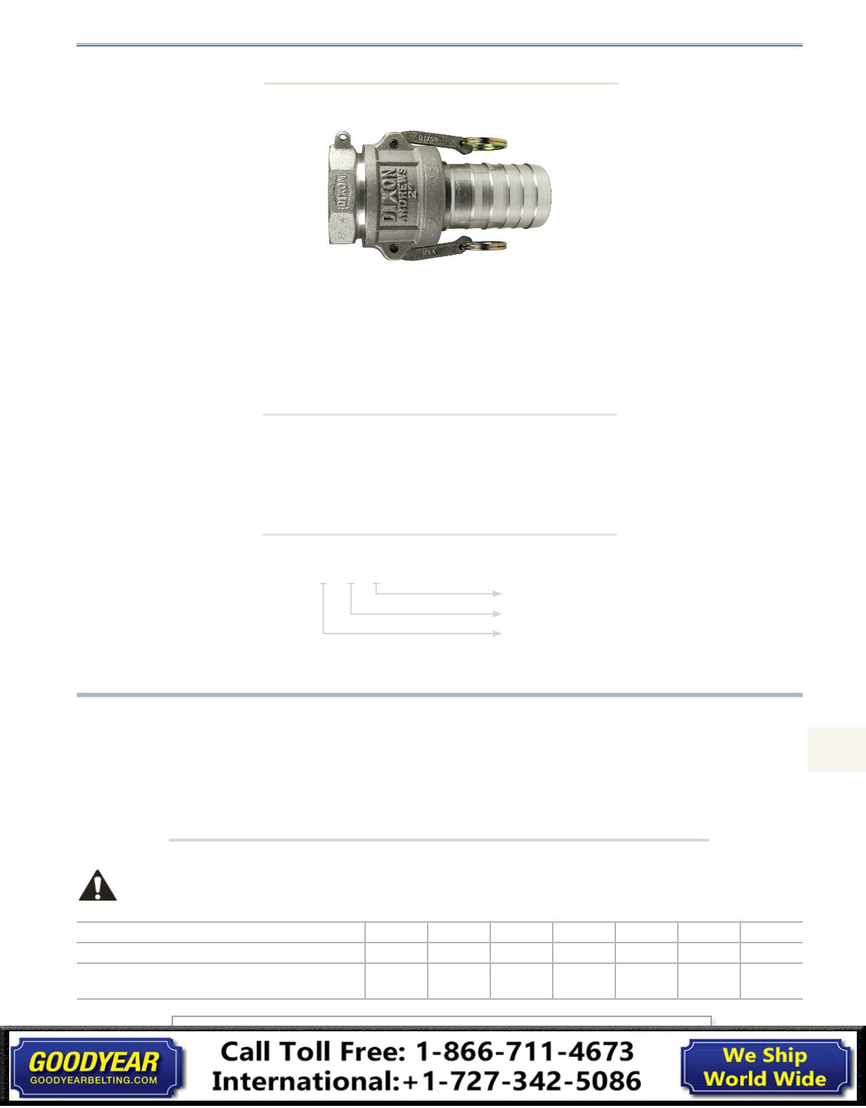
Cam and Groove
Specifications on Dixon Cam and Groove
Dixon
Features:
•
precision machined to rigid tolerances
•
durable stainless steel cam arm pins will not rust or bind, for greater strength and safety
•
recess holds gasket firmly in place - ensures proper placement
•
long shank design allows proper banding, thus eliminating the major cause of hose damage
Size represents the coupler or adapter and hose or pipe end. (i.e. 200 = 2") If the coupling is a reducing size, the coupler or
adapter is the first size. (i.e. 4030-C is 4" coupler to 3" hose shank).
Operation of Cam and Groove
1. To make connection, simply slide the adapter into the coupler and with normal hand pressure, press the cam levers down.
2. Uncoupling is as quick and simple as coupling. Just lift the cam arms and remove the adapter.
Ordering System
size
material
style
200 - A - AL
Specifications:
Pressure Ratings:
•
Dixon cam and groove couplers and adapters are produced to interchange with all product produced to Commercial Item
Description A-A-59326B.
•
No standard exists for the ½" and 8" fittings, and generally these sizes do not interchange with other manufacturers.
•
Dust caps and dust plugs are
not
to be used in pressure applications for safety and environmental reasons.
•
Designed for use with liquids
, consult Dixon for specific recommendations.
Recommendations based on the use of mating Dixon fittings at ambient temperature (
70°F
) with standard Buna-N Seal
installed. For use at elevated temperature or other unusual operating conditions, consult the factory. Dixon, Boss-Lock
and EZ Boss-Lock couplers and adapters maximum working pressure are as follows:
Size
½"
¾" thru 2"
2½"
3"
4"
5" and 6"
8"
PSI
150
250
150
125
100
75
50
PSI
(working pressure with King Crimp ferrule system)
150
250
150
150
150
75
50
All dimensions are in inches unless otherwise noted. Engineering dimensions are available upon request.
Specifications are subject to change without notice.