


 133 / 235

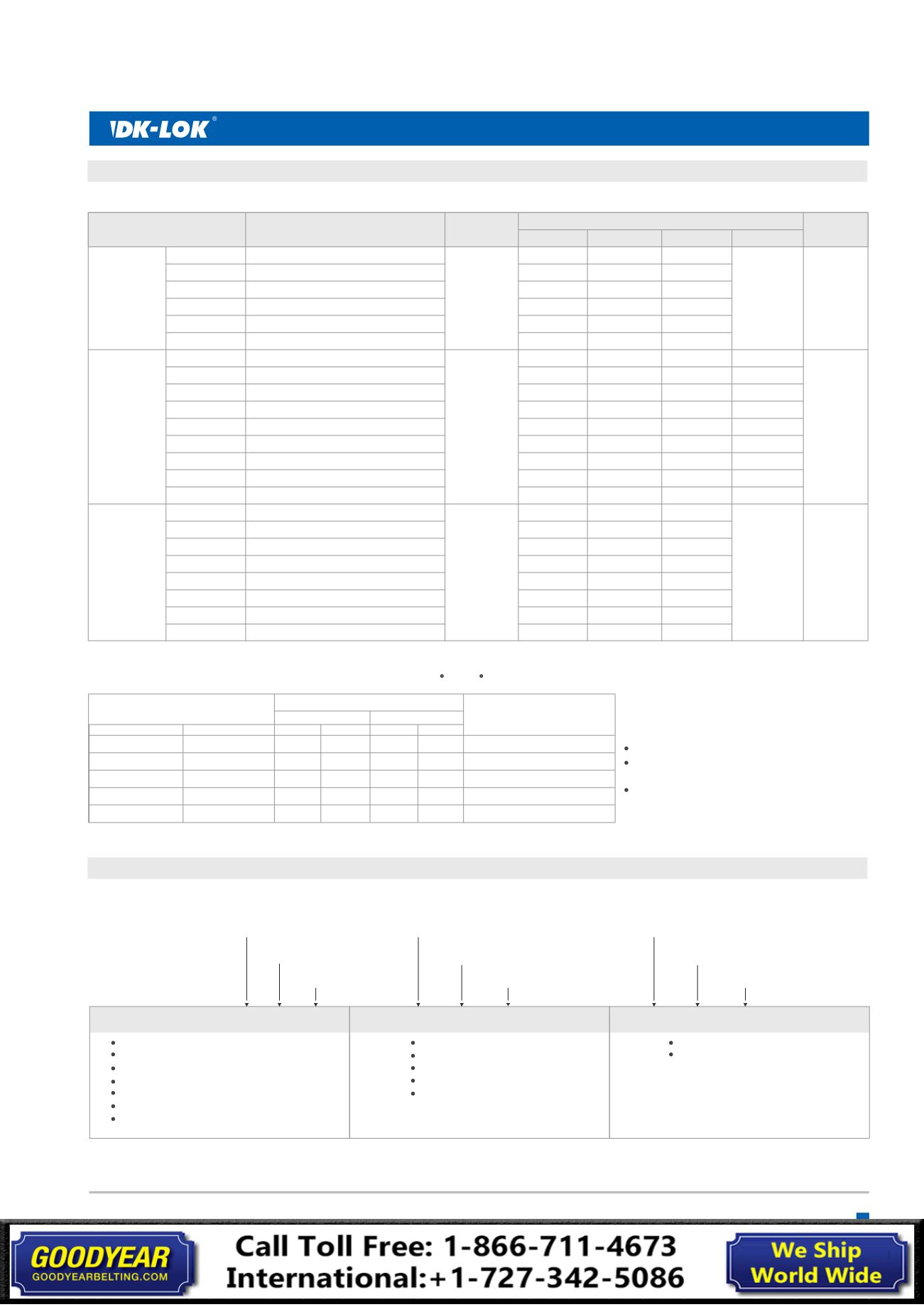
Table 4.
Spring Cracking, Reseal and Back Pressure @ 70 F (21 C)
11/16
7/8
16
19
22
-
-
-
-
6000 ( )
413
5000 ( )
344
1-1/8
1-1/2
32
40
-
-
-
-
VH36 Series Ordering Information and Dimensions
D-2T-
M-2N-
D-4T-
D-6M-
F-4N-
M-4N-
D-6T-
D-8T-
D-8M-
D-10M-
D-12M-
F-6N-
F-8N-
M-6N-
M-8N-
D-12T-
D-16T-
D-22M-
D-25M-
F-12N-
F-16N-
M-12N-
M-16N-
1/8 in. Dk-Lok
1/4 in. Dk-Lok
6 mm Dk-Lok
1/4 in. Female NPT
1/8 in. Male NPT
1/4 in. Male NPT
3/8 in. Dk-Lok
1/2 in. Dk-Lok
8 mm Dk-Lok
10 mm Dk-Lok
12 mm Dk-Lok
3/8 in. Female NPT
1/2 in. Female NPT
3/8 in. Male NPT
1/2 in. Male NPT
3/4 in. Dk-Lok
1 in. Dk-Lok
22 mm Dk-Lok
25 mm Dk-Lok
3/4 in. Female NPT
1 in. Female NPT
3/4" Male NPT
1 in. Male NPT
57.7 ( )
61.7 (
)
61.7 (
)
54.1 (
)
45.5 (
)
55.1 (
)
69.9 (2.75)
75.2 (2.96)
68.6 (2.70)
71.1 (2.80)
75.2 (2.96)
64.8 (2.55)
77.0 (3.03)
59.9 (2.36)
69.3 (2.73)
89.4 (3.52)
98.6 (3.88)
88.4 (3.48)
98.6 (3.88)
82.0 (3.23)
97.3 (3.83)
83.6 (3.29)
93.2 (3.67)
2.27
2.43
2.43
2.13
1.79
2.17
26.4 (
)
26.4 (
)
26.4 (
)
-
26.4 (1.04)
26.4 (1.04)
31.2 (1.23)
31.2 (1.23)
31.2 (1.23)
31.2 (1.23)
31.2 (1.23)
-
-
31.2 (1.23)
31.2 (1.23)
45.2 (1.78)
45.5 (1.79)
45.5 (1.79)
45.5 (1.79)
82.0 (3.23)
97.3 (3.83)
45.5 (1.79)
45.7 (1.80)
1.04
1.04
1.04
7/16
9/16
14
-
-
-
11/16
1
1
1
1
1
1
1-1/16
1
1
1-5/8
6000 ( )
413
Basic Ordering
Number
End Connections
Cv
1.8
4.7
0.67
Dimensions mm ( )
inch
H
h
L1
L
Pressure
Rating
bar
psig ( )
VH36A-
VCH36A-
VH36B-
VCH36B-
VH36C-
VCH36C-
Select valve basic ordering number, applicable seal, spring nominal cracking pressure, and body material.
How to Order
Seal Material Designator
Spring Nominal Cracking Pressure Designator
Valve Body Material Designator
1/3: 1/3 psi
1: 1 psi
3: 3 psi
10: 10 psi
25: 25 psi
S: 316 stainless steel
B: Brass
Note:
Select the spring designator from Table 1, 2, 3
and 4 of each valve Series.
V33A-D-4T-
S
BN-
1/3-
VP33B-F-8N-
B
VT-
1-
VH36C-D-16T-
S
EP-
3-
Note
: The basic ordering numbers indicated in blus are not for CNG/NGV applicable VCH36 Series vavlves.
Sour Gas Service
Materials of VH36 series valves for sour gas
service are selected in accordance with
the requirements of NACE MR0175
To order, insert-SG in the ordering number.
i.e., VH36B-D-8T-SG-S
Spring: alloy X-750/AMS5699
FKM: Nil for SS316 Valve
NBR: Nil for Brass Valve
HNBR: Nil for VCH36 CNG valves
FKM: VT
NBR: BN
EPDM: EP
FFKM: KZ
Spring Nominal
Cracking Pressure
Designator
psi
1/3
1
5
10
25
bar
0.02
0.07
0.34
0.69
1.72
bar
0
0
0.21
0.48
1.38
psi
0
0
3
7
20
Cracking Pressure Ranges
Min. Pressure Max. Pressure
psi
3
4
9
15
30
bar
0.21
Up to 6 (0.41) back pressure
Up to 5 (0.35) back pressure
Up to 2 (0.14) back pressure
Minimum 3 (0.21) Reseal pressure
Minimum 17 (1.2) Reseal pressure
0.28
0.62
1.03
2.07
Reseal Pressures
psi (bar)
Seal: ethylene propylene.
Nominal Cracking Pressure:
1/3, 1, and 5 psi (0.03, 0.07 and 0.035 bar)
7
Check Valves