Page 422 - 4300 Catalog Cover.pdf
SEO Version


4300 Catalog
Assembly / Installation
Parker Hannifin Corporation
Tube Fittings Division
Columbus, Ohio
T12
Tube End Assembly
The assembly of the tube end consists of the following two
steps:
1. Tube end preparation (cutting, deburring and cleaning)
2. Assembly and installation
Tube End Preparation
Tube end preparation is a very critical step to assure the integrity
of a tube assembly. Failure to properly perform this function can
result in leakage.The three steps in proper tube end preparation
are: cutting, deburring and cleaning.
Cutting
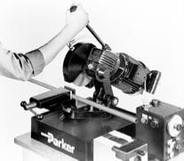
Cut tube reasonably square (within+/- 1°) usingacircular toothed
cut-off saw (see Fig. T10), or a hacksaw with a fine tooth blade
guided by a Tru-Cut Saw Guide (shown i
or other
mitre-type saw guide.
Fig. T10 – Cut-off Saw on Parker’s TP432 or TP1025
Tube Preparation Center
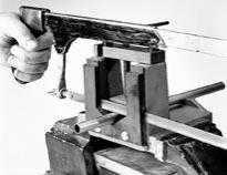
Fig. T11– Parker’s Tru-Kut Sawing Vise used with
hacksaw
A tube cutter may be used with soft tube such as copper and
aluminum. It is not recommended for steel and stainless steel
tube because it creates a large burr on the I.D., which is difficult to
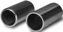
remove and creates flow restriction. For a steel or stainless steel
tubeapplication, Fig.T12 illustrates aproper cut andan improper
cut (the improper cut was performed by a tube cutter).
Improper Cut
Proper Cut
Fig. T12 – Samples of improper and proper cuts on
steel tube
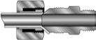
Asquarecut isessential toassurea leak-freeconnection.The fol-
lowing illustrations depict what will result from an uneven cut.
Inadequate
contact area
Possible nut
interference
Uneven bite may result from
out-of-square tube cut
Inadequate
contact area
Possible nut
interference
Too large of a gap
impedes braze flow
Fig. T13– Results of Uneven Tube Cuts
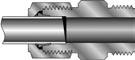
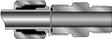
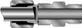
Flare Connection
Flareless Bite
Type Connection
Mechanical
Formed ORFS
Connection
Brazed ORFS
Connection
Tube End Assembly
Powered by FlippingBook Publisher