Page 418 - 4300 Catalog Cover.pdf
SEO Version


4300 Catalog
Assembly / Installation
Parker Hannifin Corporation
Tube Fittings Division
Columbus, Ohio
T8
Flange Ports
Large threaded port connections, such as SAE straight thread,
require very high torque to assemble. This makes assembly
very difficult, especially where wrench clearance is limited. Split
flange connections solve this problem by dividing the hydraulic
load among four bolts each requiring much less torque, smaller
wrenches and smaller wrench clearance.
There are two types of flange port connections:
• ISO 6162, Type 2
• SAE Code 61 4-bolt split flange
• SAE Code 62 4-bolt split flange
• ISO 6164
The 4-Bolt Split Flange consists of four main components:
• A body (flange head)
• An O-ring
• One “captive” or two “split” flange clamps
• Four bolts and washer
The four-bolt port is simply a circular opening (flow passage)
surrounded by four tapped holes in a certain pattern for accep-
tance of the flange clamping bolts. The flat surface of the port
compresses the O-ring contained in the groove in the flange
head when the clamp bolts are torqued. In some instances,
the groove is in the port and not in the flange head. The bolts,
through the clamp halves, clamp down the flange head onto the
flat surface of the port compressing and trapping the O-ring in
the groove and leaving no gap for it to extrude under pressure.
The hydraulic pressure is thus sealed by the compressed O-
ring as long as the bolts are tightened enough to maintain solid
metal to metal contact between the flange head at the outside
diameter of the O-ring and the top of the port.
Flange Port Assembly
The steps to properly assemble the flange port clamping bolts
are:
1. Inspect components to ensure that male and female port
threads and sealing surfaces are free of burrs, nicks and
scratches, or any foreign material.
2. Lubricate the O-ring.
3. Position flange and clamp halves.
4. Place lock washers on bolts and insert through clamp
halves.
5. Hand tighten bolts.
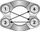
6. Torque bolts in diagonal sequence (see Fig. T10) in small
increments to the appropriate torque level listed i
low.
Port End Assembly
Dimensions and pressures for reference only, subject to change.
* Does not meet ISO 6162 specification.
Table T6 – Code 61 Flange Recommended Bolt Torque
Dash
Size
Flange
Size
Inch Bolt
(J518)
Torque
ft. lbs.
Metric Bolt
(ISO 6162)
Torque
N-m
8
1/2 5/16-18 17 ± 2
M8
25
12
3/4 3/8-16 25 ± 4.5
M10
49
16
1
3/8-16 31 ± 4.5
M10
49
20 1-1/4 7/16-14 41 ± 5
M12*
85
24 1-1/2 1/2-13 52 ± 6
M12
85
32
2
1/2-13 60 ± 6
M12*
135
40 2-1/2 1/2-13 85 ± 9
M12
95
48
3
5/8-11 144 ± 15
M16
220
56 3-1/2 5/8-11 125 ± 8
M16
220
64
4
5/8-11 125 ± 8
M16
220
80
5
5/8-11 125 ± 8
M16
220
Table T8 – Hydraulic Flange Recom-
mended Bolt Torque
Socket Screw
Bolt Circle
(LK)
Socket
Head Cap
Screws
Tightening
Torques
N-m
LK35
M6
10
LK40
M6
10
LK55
M8
25
* In general, variances of torque for soft metal ports/manifolds (ie: aluminum
block - 66% of specified torque)
* Does not meet ISO 6162 specification.
Table T7 – Code 62 Flange Recommended Bolt Torque
Dash
Size
Flange
Size
Inch Bolt
(J518)
Torque
ft. lbs.
Metric Bolt
(ISO 6162)
Torque
N-m
8
1/2 5/16-18 17 ± 2
M8
25
12
3/4
3/8-16 30 ± 4.5
M10
49
16
1
7/16-14 46 ± 4.5
M12
85
20 1-1/4 1/2-13 69 ± 6
M14*
135
24 1-1/2 5/8-11 125 ± 8
M16
210
32
2
3/4-10 208 ± 20
M20
425
Fig. T10 – Flange Bolt Tightening Sequence
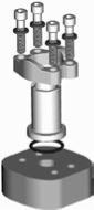
Fig. T9 – 4-Bolt Split Flange Components
Bolts
Flange
Clamp
Flange Head
O-Ring
Tapped Holes
Washers
Powered by FlippingBook Publisher