Page 335 - 4300 Catalog Cover.pdf
SEO Version


Parker Hannifin Corporation
Tube Fittings Division
Columbus, Ohio
Q3
Metric Clamps
4300 Catalog
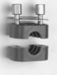
Mounting Rail Mounting
(Fig. Q2)
Use of a mounting rail is another way to assemble the clamping
system components onto a support structure. Using a mounting
rail allowsmultipleclamps tobemountedside-by-side for restrain-
ing a group of tube, pipe, or hose assemblies.The mounting rail
also provides the ability to move the location of the clamps in
one direction for easier alignment. The rail can be attached to
a support structure by welding or bolting. Once the mounting
rail is in place, rail nuts can be slid into the rail. The first clamp
half, followed by the tube, pipe or hose assembly, can then be
installed over the corresponding rail nuts. After this, the second
clamp half, the cover plate and the hex head attachment bolts
can be installed to complete the assembly.
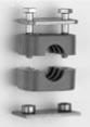
Stackin
A primary feature of the Metric Clamp system is its ability to
accommodate stacking of a series of clamps to various heights,
thus requiring a smaller footprint for mounting.To do this, simply
use the stacking bolts to mount the first clamp assembly, then
install a stacking plate over the first clamp and stacking bolts.
The second clamp assembly can then be placed over the first
clamp assembly. Complete themounting by assembling a cover
plate and using the hex head bolts to tighten the upper clamp
assembly.
Note: When stacking, the clamps must be from
the same series and group.
Introduction
TheParkerMetricClamp system is designed for restraining tube,
pipe and hose assemblies against unwanted, and potentially
harmful effects of mechanical shock and vibration forces that
are common in fluid power systems.
The clamping system is the most commonly overlooked aspect
of fluid power systemdesign.Failure to properly restrain the fluid
conducting system can result in leakage, downtime and system
malfunction, as well as significantly reduced life of tube, pipe
and hose assemblies.With the Parker Metric Clamp system, the
risk of problems resulting from mechanical shock and vibration
can be significantly reduced.
Design and Construction
Designed to meet the basic envelope dimensions of DIN 3015,
Part 1, the plastic clamp halves are interchangeable with the
ParKlamp system. The primary difference between these two
clamping systems is the utilization of inch thread hardware in
the Parklamp system, while the Metric Clamp system utilizes
metric hardware.
For convenience, the Metric Clamp system is divided into three
different series, Standard, Heavy and Twin. Each series has
correspondingcomponents, physical dimensionsandmechanical
properties. Within each series, there are a number of groups,
each with specific envelope dimensions. Components from
different series and/or groups can not be intermixed. However,
the standard and twin series can be mounted on the same
mounted rail.
How It Works
The Metric Clamp system has two primary methods for mount-
ing: weld plates and mounting rails. Clamps may be mounted
to secure a single layer of tube or stacked for securing multiple
layers.
Clamps should be mounted to a rigid structure for optimum
performance. Clamping tube, pipe or hose assemblies together
without mounting them to a rigid structure, often called “floating
clamps,” does not provide adequate support.
Proper design of a clamping system requires that the clamps be
positioned appropriately on the tube, pipe or hose assemblies.
See th
f the catalog for
more information on clamp location and spacing.
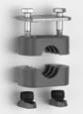
Weld Plate Mounting
(Fig. Q1)
Theweldplatemountingsystemallows theuser toattachasingle
clamp assembly to a structure of similar material (steel to steel,
etc) by welding the components together.Once the weld plate is
attached to a structure, one clamp half can be placed onto the
weld plate, followed by the tube, pipe or hose assembly. Next,
the second plastic clamp half can be placed on the tube, pipe
or hose assembly, followed by the cover plate. To complete the
assembly, the Hex Head attachment bolts are inserted into the
assembly and tightened.
Assembly and Installation
Please refer t
for the assembly and installation
instructions for Metric Clamps.
Fig. Q1 – Weld Plate
Assembly
Fig. Q2 – Mounting Rail
Assembly
Fig. Q3 – Stacked
Assembly
Powered by FlippingBook Publisher