Page 66 - 4300 Catalog Cover.pdf
SEO Version


C8
Parker Hannifin Corporation
Tube Fittings Division
Columbus, Ohio
Triple-Lok
®
37° Flare Tube Fittings
4300 Catalog
International Acceptance
The Triple-Lok male flare end is attachable to either inch tube,
metric tube or a hose assembly. Parker offers many different
port thread options for the various international hydraulic ports
available. This is one of the primary reasons for its worldwide
acceptance.Parker has traditionally offered a “MetricTriple-Lok”
product line directed at the Metric, ISO-6149 and BSPP port us-
ers. Rather than carrying a separate catalog section, this range
of international fittings has been integrated into the traditional
“Triple-Lok” section.
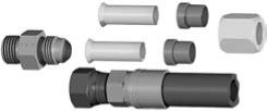
To illustrate the versatility of Triple-Lok, refer to Fig. C3. A single
37° fitting body will accept both inch and metric tube sizes by
simply changing the sleeve. Thus, a dedicated line of sleeves
is offered for inch and metric tube. The universal tube nut and
fitting body is used with either inch or metric tube, thus saving
on component costs and making the Triple-Lok fitting more
versatile. Also, the 37° body without the nut and sleeve is very
popular as a hose adapter.
Study the following example illustrating the options with an SAE
–8 (1/2”) Triple-Lok fitting:
1. Fitting with a –8 (1/2”) sleeve and –8 (1/2”) tube nut can
connect to a 1/2” o.d. flared tube.
2. Fitting with a 12 mm sleeve and –8 (1/2”) tube nut can
connect to 12 mm o.d. flared tube
3. Fitting without a nut and sleeve can be used as a 1/2” hose
adapter when connected to a hose swivel.
Table C2 illustrates an even clearer picture of the flexibility of
the Triple-Lok 37° system. It shows every “convertible sleeve”
connection for the 37° flare design. For example, if 25 mm tube
is being used, a –16 (1”) 37° flare fitting together with a 25 mm
(TXS25) sleeve and a standard –16 (1”) flare fitting nut would
be all the necessary components to connect and seal a 25 mm
flared tube assembly.
Tube Wall Thickness – Inch and Metric
Minimum/Maximum tube wall thickness is based on the pres-
sure holding capacity of the fittings and subject to maximum
wall thickness limitations.
Inch Tube
Metric Tube
Hose Assembly
Fig. C3 – Triple-Lok’s Adaptability to Inch Tube, Metric Tube, or
Hose Assemblies
Table C2 – Triple-Lok Convertible Sleeve Connections
Table C3 – Wall Thickness Chart for Inch and Metric Tubing
Inch
Sleeve
Metric
Sleeve
Universal
Tube Nut
Universal
Triple-Lok Body
FITTING
DASH
SIZE
TUBE
O.D.
METRIC TUBE
SLEEVE
PART #
NUT
PART #
-4
6mm TXS6
4 BTX-S
-5
8mm 5 TX-S
5 BTX-S
-6 10mm TXS10
6 BTX-S
-8 12mm TXS12
8 BTX-S
-10 14mm TXS14
10 BTX-S
-10 15mm TXS15
10 BTX-S
-10 16mm 10 TX-S
10 BTX-S
-12 18mm TXS18
12 BTX-S
-12 20mm 20-12 TX-S 20-12 BTX-S
-14 22mm TXS22
14 BTX-S
-16 25mm TXS25
16 BTX-S
-20 28mm TXS28
20 BTX-S
-20 30mm TXS30
20 BTX-S
-20 32mm TXS32
20 BTX-S
-24 35mm TXS35
24 BTX-S
-24 38mm 24 TX-S
24 BTX-S
FITTING
DASH
SIZE
WALL THICKNESS –
INCH TUBE
WALL THICKNESS –
METRIC TUBE
O.D. WALL THICKNESS O.D. WALL THICKNESS
(in.)
Min.
(in.)
Max.
(mm)
Min.
(mm)
Max.
-2 1/8 0.010 – 0.035 –
–
-3 3/16 0.010 – 0.035 –
–
-4 1/4 0.020 – 0.065 6.0 0.5 – 2.0
-5 5/16 0.020 – 0.065 8.0 0.5 – 2.0
-6 3/8 0.020 – 0.065 10.0 0.5 – 2.0
-8 1/2 0.028 – 0.083 12.0 1.0 – 2.0
-10 5/8 0.035 – 0.095 14.0 1.0 – 2.5
-10 5/8 0.035 – 0.095 15.0 1.0 – 2.5
-10 5/8 0.035 – 0.095 16.0 1.0 – 2.5
-12 3/4 0.035 – 0.109 18.0 1.0 – 3.0
-12 3/4 0.035 – 0.109 20.0 1.0 – 3.0
-14 7/8 0.035 – 0.109 22.0 1.0 – 3.0
-16
1 0.035 – 0.120 25.0 1.0 – 3.0
-20 1 1/4 0.049 – 0.120 30.0 1.5 – 3.0
-20 1 1/4 0.049 – 0.120 32.0 1.5 – 3.0
-24 1 1/2 0.049 – 0.120 38.0 1.5 – 3.0
-32
2 0.058 – 0.134 50.0 1.5 – 3.5
Powered by FlippingBook Publisher