Page 449 - 4300 Catalog Cover.pdf
SEO Version


4300 Catalog
Assembly / Installation
Parker Hannifin Corporation
Tube Fittings Division
Columbus, Ohio
T39
Tools for Tube Bending
For smooth, wrinkle free tube bending without excessive flatten-
ing, there are a number of benders that can be selected.Consult
the specific bender’s instruction bulletins for CLR (centerline
radius), wall thickness, and tubematerial recommendations and
limitations. For crank and hydraulic benders, utilize both the
mandrel bending determination chart (Fig. T56) and the Parker
Bender Capacity Guides o
1. Hand held lever type benders
(see
).
Individually sized for tube sizes 1/8” through 1” and 6mm
through 25mm.
Fig. T53 — Hand held tube bender
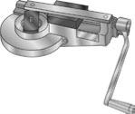
2. Manual crank, table mount or vise mount benders:
1) Model 41
or bending 1/4” through
3/4” O.D. tube or 6mm through 20mm.
2) Model 42
For bending 1/4” through
1 1/2” O.D. tube or 6mm through 38mm.
Fig. T54 — Manual crank bender
3. Hydraulically powered bender
Model 63
or bending 3/8” through 2” O.D.
tube or 10mm through 50mm.
Fig. T55 — Hydraulic bender with portable table for mandrel
bending
Mandrel Bending Tools
When bending thin wall tube it may be necessary to insert a
mandrel into the tube to prevent excessive distortion, flatten-
ing or wrinkling. To determine whether mandrel bending is
required, see the Mandrel Bending Requirements Chart and
example below.
To accomplish such bending, a mandrel, mandrel rod, and a
mandrel rod stop assembly are required.The rod stop assembly
holds the end of the mandrel rod in proper alignment with the
tube while the mandrel, which is threaded onto the other end of
the mandrel rod, supports the tube on its I.D., thus preventing
tube kinking or flattening during bending.
Example:
Determine if it’s necessary to usemandrel for bending
3/4 x .049 steel tube through a 3” bend radius without exces-
sive flattening.
Centerline Radius/Tube Outside Diameter = 3 / .75 = 4
Outside Diameter / Wall Thickness = .75/.049 = 15.3
Intersection of these two ratios on the graph falls within the area
indicating that no mandrel is required. Note, however, that for
the same tube O.D. at a smaller bend radius (e.g. 2”) or with a
thinner wall thickness (e.g. .035”), a mandrel would be required
for preventing excessive flattening.
If the tube wall is very thin, then a plug mandrel alone may not
be adequate to prevent wrinkling. In such cases, special ball
type mandrels and wiper shoes may be necessary (Se
or illustrations of plug and ball type mandrels). As a rule
of thumb, if the tube wall thickness is less than 7% of the tube
O.D. then mandrel bending is recommended.
Fig. T56 — Mandrel bending requirements chart
0 10 20 30 40 50 60 70 80 90 100 110 120 130 140 150
1
Ratio of
Outside Diameter (OD)
Wall Thickness (TK)
2
3
4
5
6
7
8
9
10
11
12
13
14
Ratio of
Centerline Radius (CL RAD)
Outside Diameter (OD)
TK
CL RAD
O.D.
Not Practical
Multiple Ball Mandrel
One Ball Mandrel
Plug
Mandrel
No Mandrel
Mandrel Bending Requirements Chart
0
45
90
135
0
90 45
135
Tools for Tube Bending / Mandrel Bending
Dimensions and pressures for reference only, subject to change.
Powered by FlippingBook Publisher