Page 427 - 4300 Catalog Cover.pdf
SEO Version


4300 Catalog
Assembly / Installation
Parker Hannifin Corporation
Tube Fittings Division
Columbus, Ohio
T17
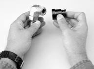
Fig. T24 – O-Ring installation using the CORG
assembly tool
2. Cleaning the tube end:
All oil and oxide buid-up must be
removed from the tube end for at least the length of the braze
joint. Oil may be removed by using an oil-free solvent. Oxide
build-up may be removed by pickling or by lightly sanding
with an aluminum-free emery paper.
3. Fixturing the parts for brazing:
Care should be taken so
the braze fixture allows the sleeve to settle and bottom on
the tube completely during heating. Since the Seal-Lok fitting
sleeve isdesigned for aslipfit, this shouldhappeneasily.Short
tubes can be brazed in the vertical position. On longer tubes,
the joint may need to be in the horizontal position, requiring
a slight nudge to seat the sleeve on the tube.
4. Applying flux:
Apply proper
flux to
tube end (about 1½
sleeve lengths) and sleeve’s face and outside surface. Insert
appropriate braze ring in the sleeve and place the sleeve on
end of the tube.The flux helps protect the parts fromoxidizing
and promotes braze flow.
5. Heating the part:
Apply heat uniformly to the joint by using
a multi-flame torch as shown i
r with an induction
braze unit. Proper brazing involves heating the assembly to
brazing temperature and flowing the filler metal through the
joint. Heat should be applied broadly and uniformly to the
tube as well as the Seal-Lok sleeve. Keep in mind that thicker
fitting and tubing sections take longer to heat. The entire
assembly should heat to brazing temperature at about the
same time. The braze alloy will always flow towards the area
of higher temperature. The pre-formed braze ring has been
placed inside the joint area—the last area to reach melting
temperature.Therefore, when you see the brazematerial flow
to the outside of the joint, you know the joint is complete. If
the sleeve does not settle, a slight pressure will cause the
sleeve to settle, completing the braze joint.
6. Cleaning the brazed joint:
After stopping heat application,
allow about 10 seconds for the braze alloy to solidify. Then,
immerse the joint in hot water (approx. 140°F.). To make
cleaning easier, add Parker Braze Cleaner to the hot water.
This sudden cooling cracks the braze flux residue, making it
easier to remove. Any remaining residue can be removed by
careful wire brushing, making sure not to scratch the sealing
surface of the sleeve.
7. Corrosion protection after brazing:
This is an extremely
important step following brazing and even more so following
the use of a braze cleaner. Braze cleaners such as Handy
and Harman Post Braze Cleaner available from Parker and
Bernite 45
1
which are used to facilitate the removal of residual
flux after brazing, are generally corrosive.The residue left on
the surface by the cleaner, especially on the I.D. of the tube,
can cause rusting in carbon steel tubes rather quickly, if it
is not neutralized. Therefore, it is important to neutralize the
cleaner residue after cleaning with a solution such as Bernite
136
2
(mix 4 ounces of Bernite 136 with one gallon of water).
If the brazed parts are not to be used soon after brazing,
a coating of rust inhibitors such as WD-40
3
or SP-350
4
is
recommended for the braze and heat affected area.
1 & 2 ) Products of Bernite Products, Inc. 84 New York, Westbury, NY 11500
(516) 338-4646.
3 ) A product of WD-40 Company, San Diego, CA 92220.
4 ) A product of CRC Chemicals, USA, Warminister, PA 18974 (215) 674-4300
Inspection of Brazing
Inspect the braze for a fillet all the way around the tube at the
far end (small diameter) of the sleeve.
Caution:
If there are gaps in the fillet, the joint may not be sound.
In this case, rebrazing is recommended.Remove the sleeve and
rebraze a new one in its place.
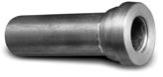
Fillet all the way
around the tube
No braze alloy overrun
on sealing surface
Fig. T23 – Brazed fitting
Inspect the sealing surface. There should be no braze alloy
overrun or build-up on this surface. If there is build-up, remove it
with emery paper, being careful not to scratch the seal surface.
If this is not possible, remove the old sleeve and rebraze a new
one in its place.
Final Installation
The following steps are required for final installation of the
Seal-Lok fitting:
1. Ensure that the correct O-ring is properly installed in the
groove of the fitting, if not already pre-installed by the fitting
manufacturer (Parker provides Seal-Lok fittings with pre-in-
stalled O-rings). Since Seal-Lok is machined with the captive
O-ring groove (CORG), it is recommended that a CORG
assembly tool be utilized, as shown in Fig. T24. To properly
use the assembly tool, follow these steps
• Position the O-ring inside the CORG assembly tool against
the pusher.
• Position the tool over the Seal-Lok tube end until the end is
bottomed in the tool.
• Push the plunger of the tool until the O-ring is inserted and
seated into the groove.
Seal-Lok Assembly
Powered by FlippingBook Publisher