Page 366 - 4300 Catalog Cover.pdf
SEO Version


Parker Hannifin Corporation
Tube Fittings Division
Columbus, Ohio
S16
4300 Catalog
Equipment
Dimensions and pressures for reference only, subject to change.
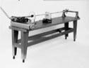
Fig. S32 — Bender Table
(equipment not included)
Fig. S33 — Mandrel Graph Chart
Bender Table (With Locking Casters) for HB632
Sturdy, heavy all steel construction, strongly braced to keep
bender, mandrel rod, and mandrel rod stop assembly rigidly
aligned. All holes are pre-drilled at factory to accommodate
the HB632 bender and rod stop assembly.
DIMENSION:
H – 36” W – 30” L – 10’
NOTE:
Table is supplied with locking casters for ease of
mobility.
Part No.
520515
Mandrel Bending Components
When bending thin wall tube it may be necessary to insert a
mandrel into the tube to prevent excessive distortion or flat-
tening.To accomplish such bending, a Mandrel, Mandrel Rod,
and aMandrel Rod Stop Assembly are required.The Rod Stop
Assembly holds the end of the Mandrel Rod in proper align-
ment with the tube while the Mandrel, which is threaded onto
the other end of the Mandel Rod, supports the tube on its I.D.,
thus preventing tube kinking or flattening during bending.
The following parts are required for mandrel bending with the
412 and 424 bender:
Part Name
Part No.
Mandrel Rod Stop Assembly ......................................................
550571
Stop Assembly Adapter Riser (424 only)....................................
631154
Mandrel Rods ............................................................................. Se
Mandrel....................................................................................... Se
The following parts are required for mandrel bending with the 632 bender:
Part Name
Part No.
Mandrel Rod Stop Assembly ......................................................
631141
Mandrel Rods ............................................................................. Se
Mandrel....................................................................................... Se
Example:
Tube O.D.: 2”
Wall Thickness: 0.095”
Centerline Radius: 8”
Vertical Axis = 8” = 4
2”
Horizontal Axis = 2”
˜
21
.095”
Answer: Plug Mandrel required
Benders
Powered by FlippingBook Publisher