Page 302 - 4300 Catalog Cover.pdf
SEO Version


N10
Parker Hannifin Corporation
Tube Fittings Division
Columbus, Ohio
4300 Catalog
Diagnostic, Orifice, Bleed Adapters,
Screen and Specialty Fittings
Dimensions and pressures for reference only, subject to change.
TUBE
FITTING
PART #
END SIZE BODY
HEX
(in.)
H
(in.)
L
REF.
(in.)
LL
REF.
(in.)
STANDARD
Pressure
(x 1,000 PSI)
1
Static
-S
Dynamic
-S
4 P5ONBA
7/16-20 UN/UNF-2A 11/16 11/16 2.05 1.62 10.0 6.0
1/4 HPBA
1/4-18 NPTF 11/16 11/16 2.20 1.86 10.0 6.0
Bleed Adapters
Entrapped air is a major contributor to inefficient operation.
Typically, bleeding hydraulic systems is done by “cracking”
a connection to “bleed off” the entrapped air. This practice
is not recommended, especially in larger size fittings where
high forces can exist.Parker’s bleed adapters are especially
beneficial in applications where elastomeric seals (O-rings)
can be extruded and/or damaged during bleeding such as
with Parker’s Seal-Lok fittings.
Parker’s bleed adapters are designed specifically for instal-
lation directly to ORFS (O-Ring Face Seal) type fittings
or into SAE/NPT manifolds and valves where bleeding is
often required.
Features
• Bleed hydraulic systems without “cracking” hydraulic
connections
• Uses standard automotive bleed screw design
• Bleed screw is permanently crimped into body hous-
ing, for blowout prevention
• In-port options with SAE and NPT male studs
• Tube/hose connection options to male and female
ORFS
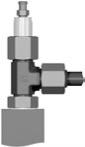
ORFS Bleed Adapters
PNLOBA
FNLBA
ORFS Tube Nut sold separately
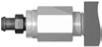
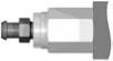
Port Bleed Adapters
4 P5ONBA
1/4 HPBA
Bleeding Hydraulic Systems with Parker
Bleed Adapters
Whenever possible, the bleed adapter should be mounted at
the highest point within the hydraulic system. The trapped air
can be relieved while the system is running at low pressure. To
bleed, loosen the bleed screw 1/2 turn counterclockwise. After
the hydraulic fluid begins to run freely from the bleed screw, the
bleed screw should be re-tightened.
Bleed Screw Tightening Torque:
35-40 in.-lbs.
Warning:
When bleeding hydraulic fluid, operate the system
below 500 psi. To avoid injury, ensure that all persons are clear
of the path of discharge. Another recommended practice is to
attach a section of hose over the bleed screw/adapter to direct
oil away from the area and to reduce oil spillage.
1
TUBE
FITTING
PART #
END
SIZE
F
(in.)
H
(in.)
L
(in.)
STANDARD
Pressure
(x 1,000 PSI)
1
(in.)
Static
-S
Dynamic
-S
4 PNLOBA
1/4 - 11/16 1.90 12.0 9.2
6 PNLOBA
3/8 -
3/4 1.97 12.0 9.2
8 PNLOBA
1/2 -
7/8 2.07 12.0 9.2
10 PNLOBA
5/8 - 1 1/16 2.19 11.0 6.0
12 PNLOBA
3/4 -
1 1/4 2.27 11.0 6.0
16 PNLOBA
1 -
1 1/2 2.35 9.5
6.0
20 PNLOBA
1 1/4 -
1 3/4 2.41 8.0
6.0
24 PNLOBA
1 1/2 -
2 1/8 2.48 6.5
5.0
8 FNLBA
1/2 1.63 15/16 2.07 12.0 9.2
10 FNLBA
5/8 1.63 1 1/8 2.17 11.0 6.0
12 FNLBA
3/4 1.63 1 3/8 2.21 11.0 6.0
16 FNLBA
1 1.63 1 5/8 2.21 9.5
6.0
20 FNLBA
1 1/4 1.63 1 7/8 2.21 8.0
6.0
24 FNLBA
1 1/2 1.63 2 1/4 2.21 6.5
5.0
Seal-Lok Bleed Adapter
(Sizes -8 thru -24)
For use with
Seal-Lok Fittings
Straight Thread Bleed Adapter
Size 4 (7/16-20 UNF)
For use with SAE Straight
Thread Ports
Pipe Thread Bleed Adapter
1/4 NPT
For use with Pipe Thread
Ports
1)
2)
1)
2)
2)
1)
Notes:
1) Standard automotive
bleedscrew.
2) Locking crimp prevents
screw from being completely
unthreaded.
Powered by FlippingBook Publisher