Page 103 - 4300 Catalog Cover.pdf
SEO Version


Parker Hannifin Corporation
Tube Fittings Division
Columbus, Ohio
D5
4300 Catalog
Ferulok
®
Flareless Bite Type Fittings
Dimensions and pressures for reference only, subject to change.
Seal
with
body
Seal
with
tube
Table D2 — Recommended Tube Wall Thickness
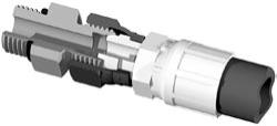
Fig. D3 – Ferulok Fitting with Hose Assembly
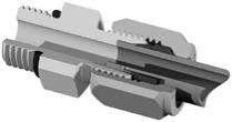
Fig. D2 – Assembled Ferulok Fitting with Tube
How Ferulok Fittings Work
As mentioned in the introduction, the ferrule in the Ferulok fit-
ting forms pressure tight seals with the tube and the fitting body.
These seals are the result of several key characteristics graphi-
cally shown in Fig. D2. Below are detailed explanations of each
of these key features.
A. When properly assembled, the wedging action of the Ferulok
designwill cause the end of the tube topress firmly against the
seat in the body. This action will cause the tube to develop a
small indentation circumferentially on the bottom of the tube.
This indentation serves as a good post assembly inspection
criterion.
B. As the ferrule moves forward, it contacts the tapered seat
of the body, which causes the ferrule to cam inward into
the tube. The leading edge of the hardened ferrule makes
a clean 360° cut into the outside diameter of the tube. This
cut is often termed a “bite” and thus “bite type fitting”. As the
ferrule makes its bite, a small ridge of material is plowed up
in front of the ferrule. This intimate contact of the tube ridge
with the ferrule’s front face and bite edge gives the fitting its
ability to retain high pressure without leaking or blowing off.
A second seal point is also created between the now bowed
ferrule and the fitting body seat.
C. As the ferrule bites into the tube, the mid section will bow
and the inside diameter of the back area firmly grips the
tube. This action keeps the stresses, caused by flexural and
vibration loading, from being concentrated in the bite area.
The “compression grip” at the back end is a key factor for long
life in rigorous applications.
When properly assembled to the recommended tube, Ferulok
fittings will consistently seal until the applied pressure is great
enough to cause tube burst.
Although not as common, Ferulok fittings can be purchased
without nuts and sleeves for use as a hose adapter (Fig. D3).
Sealing occurs between the 24° cone of the fitting body and the
hose swivel as shown.
Assembly and Installation
Please refer t
r the assembly and installation in-
structions for Ferulok
®
fittings.
Tube Recommendation
Maximum tube wall thickness is based on the pressure holding
capability of Ferulok fittings.Tubes above the recommended range
can be used. However, the pressure holding capability of the as-
sembly will be limited to the fitting capacity. The proper Ferulok
assembly procedures as outlined
this catalog
are critical to the performance of the fitting. Steel Ferulok works
best with seamless or welded and drawn fully annealed tube, SAE
J356, SAE J524, SAE J525 (max. hardness, RB72) or equivalent
specification steel tube. For stainless steel Ferulok fittings, types
304 and 316 of ASTM A269, ASTM A213 (max. hardness, RB90)
or equivalent stainless steel tube is recommended.
Ferulok fittings are also suitable for use with soft metal tube and
various types of plastic tubes such as nylon, polyethylene, etc.
When used with plastic tube, it is strongly recommended that a
tube insert, such as T23UI, be used to prevent tube pull out due
to tensile loading.
r other combi-
nations of tube and tube fitting materials not shown.
A
B
C
Seal
Compression
grip
Size
Steel
Stainless Steel
O.D.
Inches
Dash
Number
Minimum
Wall
Thickness
Maximum
Wall
Thickness
1/8
-2
0.010
0.035
3/16
-3
0.020
0.049
1/4
-4
0.028
0.065
5/16
-5
0.028
0.065
3/8
-6
0.035
0.095
1/2
-8
0.049
0.120
5/8
-10
0.058
0.120
3/4
-12
0.065
0.120
7/8
-14
0.072
0.120
1
-16
0.083
0.148
1 1/4
-20
0.095
0.188
1 1/2
-24
0.095
0.220
2
-32
0.095
0.220
Powered by FlippingBook Publisher