Page 82 - ParkerQuickCouplingCatalog38002010
SEO Version


Quick Coupling Division
8145 Lewis Road • Minneapolis, MN 55427
www.parker.com/quickcouplings
B-38
Hydraulic Quick Couplings
B
Hydraulics
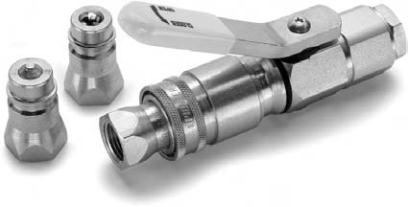
Connect Under Pressure Couplings
9200 Series
3
8
6
5
2
Features
1. The lever operates a cam that mechanically locks both
valves into either the “open” or “closed” position.
“Closed,” the flow is shut off at the coupler, allowing easy
zero-pressure connect and disconnect.
“Open,” the valves are locked in the open position in both
coupler and nipple. In this position the valves are
unaffected by hydraulic surges.
2. Parker design eliminates back flow-checking. The positive
lock of the cam prevents hydraulic surges from forcing the
valve closed, which avoids flow checking and disrupting
equipment performance.
3. Valves close automatically if coupling is accidentally
disconnected.
4. The 8010 Series nipples used with the 9200 coupler is an
industry standard that meets ISO 5675 requirements.
5. Rugged, reliable ball valve and induction hardened locking
ball groove prevent Brinelling and prolong coupling life.
6. Turning the lever without the nipple in place will NOT result
in oil flow.
7. The Lever Coupler is covered by patent numbers:
#3680591 and #4009729.
8. New easy action sleeve aids connect and disconnect.
Applications
The Parker 9200 lever coupling is designed with a lever-
operated cam that opens and closes the valves in both
coupling halves, positively locking them into place. This allows
the couplings to be easily connected and disconnected while
under pressure. The 9200 couplings can functionally replace
a Double Shut-Off quick coupling and two high pressure ball
valves. By simply turning the lever to the “closed” position the
hydraulic lines on a piece of machinery or mobile equipment
may be disconnected either for maintenance or equipment
changeovers.
Note:
Protective dust plugs and caps play a crucial role in the
life of a quick coupling and no purchase of a hydraulic quick
coupling is complete without the selection of an appropriate
dust plug and cap. See pages noted in Table of Contents for
dust plugs and caps for the Parker full line of hydraulic
couplings.
Specifications
Body Size (in.)
1/2
Rated Pressure (PSI)
3000
Rated Flow (GPM)
12
Temperature Range (std seals)
-40° to +250° F
Performance
9200 Series (1/2")
Test Fluid: Oil - 200 SUS
0
10
20
30
40
50
60
70
80
90
0
2
4
6
8
10
12
14
16
18
Flow in USGPM
Pressure Drop in PSID
1/2"
7
1
4
Powered by FlippingBook Publisher