Page 15 - LegrisTransairCatalog2010
SEO Version


H2
Ø29
L
Ø4
Transair
®
H H2 L
6699 04 65
82
25 124,5
Plug
L1
L
ØG
ØD
ØD
Transair
®
G L L1
14
3126 14 00TR
16
49
23,5
0,005
kg
3126
Female stud fitting, BSP parallel
F
H
ØD
C
E
ØD C
Transair
®
E F H
14 G3/8
3114 14 17TR
14
22
42,5
3114
H1
H
H2
L1
L2
L
ØD
Ø40
F
ØD
Transair
®
F H H1 H2 L L1 L2
14
6699 04 64
24 28 29,5 44,5 136,5 109,5 20 0,510
kg
2
1
3
1
2
In order to meet users requirements,
Transair
®
air distribution columns can
be installed on the work-bench or within the production area.
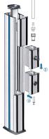
Installation
Columns
Wall and floor fixing or floor and ceiling fixing
1- Fix the mounting bracket
on the wall
2- Fix the column
3- Screw sub-base to the floor
1- Fix the sub-base
to the floor
2- Release the cylinder
to lock the column.
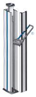
1- Measure and cut at the required height
2- Connect the modules together
3- Fix into the column
Modules
To plug the end of a module.
To connect modules to braided PVC hose, using hosetail adaptor EF26 – see Page 26.
The pilot valve module includes :
- pneumatic ON/OFF switch, maximum operating pressure 10 bar
- twin polyurethane tube, 10m length, 4mm OD
PVC hose 1025V
(page 27)
Hosetail adaptor EF26
(page 26)
Female stud fitting
3114 14 17TR
Plug
3126 14 00TR
Powered by FlippingBook Publisher