Page 117 - Goodyear2011PTCatalog
SEO Version


P O W E R T R A N S M I S S I O N P R O D U C T S
G E N E R A L I N F O R M A T I O N
115
G E N E R A L I N F O R M A T I O N
2 0 1 1
T
e c h n i c a l
I
n f o r m at i on
Follow all safety policies and requirements of federal, state, and
local authorities, as well as the regulation of the employer, when
working on power equipment. Always lock out the power source
to the machinery before performing any work.
P
r e pa r at i o n
OBJECTIVE:
Verify that all necessary tools and parts are avail-
able and ready for installation.
1. Eagle NRG
™
belts and sprockets are identified with a
unique Color Spectrum System. The seven colors used
for identification are Yellow, White, Purple, Blue, Green,
Orange, and Red. Each color represents a different size so that
Blue belts are made to operate with Blue sprockets. Make sure
the same color belt and sprockets have been obtained. When
installing Falcon HTC
®
, Hawk Pd
®
and Blackhawk Pd
®
, it is
also important that the correct sprocket width is used.
2. The following tools are recommended for proper belt and
sprocket installation.
• Straightedge
• Tape measure
• Socket and open-end wrenches • File and sandpaper
• Torque wrench
• Clean cloth
• Belt tension gauge
• Deflection force values
• Laser Alignment
for tensioning the belt
3. Make sure the components are ready for installation. Clean
all shafts, removing any nicks or burrs. Clean all mating
surfaces of the sprocket, bushing, and shaft. No lubrication
or anti-sieze solution should be used on any of these surfaces,
including threaded holes. Use of lubrication can create higher
torque, which will cause premature failure.
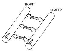
4. Make sure the shafts are true and parallel by accurately
measuring the distance between the shafts at three points
along the shaft. The distance between the shafts should be the
same at all three points as shown. Also make sure the shafts
are rigidly mounted. Shafts should not deflect when the belt
is tensioned.
S
p r o c k e t
& B
u s h i n g
I
n s ta l l at i o n
OBJECTIVE:
Align the sprockets and secure them to the shafts.
1. For conventional mounting, insert bushing into the sprocket,
aligning the tapped holes in the bushing flange with the
drilled holes in the sprocket hub.
2. Insert capscrews through the drilled holes and into the tapped
holes.
3. Insert the key into the keyseat of the shaft.
S
p r o c k e t
I
n s ta l l at i on
Shaft 1
Shaft 2
See pages 129 – 130 for tools offered and how to order.
Powered by FlippingBook Publisher