Page 47 - ExpansionJointsCatalog2010
SEO Version


™
530
STYLE
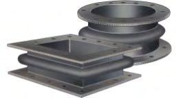
ARCH-DESIGN for ultra high movements
PROCO Style 530 Arch-Type Duct Connectors:
The least economical of the integrally flanged
designs, the Style 530 is predominately used for applications where movements are large
and face-to-face space is a premium.The duct connector is manufactured in an Arch-Design
configuration with a minimum of one (1) to two (2) plies of reinforced fabric vulcanized into
a homogeneous product that is 3/1/6", 1/4" or 3/8" thick. The flanges shall be an integral part
of the expansion joint. The Style 530 is manufactured with a premolded arch. The arch
continues through the corner and straight sections and shall be fully developed when in the
neutral installation position. Listed below is information regarding the Style 530 non-metallic
duct connectors:
System Design Considerations:
In designing the Series 500, Style 530 non-metallic duct
connector, several considerations must be taken into account to ensure long lasting service.
• System Media:
The designer and/or requesting party should define the system me-
dia to determine the correct elastomer for each application. Evaluation of the gas/air
composition should be made during design of the non-metallic fan/duct connector. Abra-
sion characteristics and external environment conditions should also be taken into ac-
count when specifying the fabric element.
• System Temperature:
The system operating temperature is of primary importance to
the design of a non-metallic fan/duct connector, although the system design is gener-
ally specified. It is important to distinguish between operating and design as “design”
can include a significant safety factor which may result in an upgraded material or de-
sign selection.
• System Pressure:
Normal operating pressures and maximum pressures (positive
and negative) under upset conditions should be specified. Combinations of pressures
and temperatures should be specifically identified.
• Movements:
Movements consist of thermal growth resulting from both operating
and upset conditions. Individual movements resulting from both conditions should be
specified. Maximum installation misalignment should also be taken into account to de-
termine if the non-metallic fan/duct connector design is capable of reacting to a combi-
nation of the total maximum movements.
PROCO
Material
Code
BB
Chlorobutyl
300
°
EE
EPDM
3/16"
1
300
°
±
2
HH
Hypalon
®
225
°
NH Neoprene/Hypalon
®
1/4"
2
225
°
±
3
NN
Neoprene
212
°
NP
Neoprene/Buna-N
3/8"
2
212
°
±
5
VV
Viton
®
400
°
Style 530 Available Materials
For Specific Elastomer
Recommendations, See:
PROCO
™
“Chemical To Elastomer Guide”
Maximum
Pressure
Rating (PSI)
Maximum
Operating
Temp
°
F
No. of
Reinforcement
Plies
Nominal
Body
Thickness
Elastomer
Styles
530
2.25
1.25
1.25
2.75
1.5
1.5
3.5
2.0
2.0
Maximum Movement Capabilities
Axial
Co
mpression
(In
ches)
6" Face To Face
9" Face To Face
12" Face To Face
Axial
Extension
(Inches)
Lateral
Offset
(Inches)
Axial
Compression
(Inches)
Axial
Extension
(Inches)
Lateral
Offset
(Inches)
Axial
Compression
(Inches)
Axial
Extension
(Inches)
Lateral
Offset
(Inches)
Non-Metallic Fan/Duct Connector Weight
(pounds per square foot of periphery)
Nominal
Body
Thickness
Elastomers
Retaining
Rings/Bars
Linear/Foot
Chloro-
butyl
Neoprene/
Hypalon
®
Neoprene/
Buna-N Viton
®
Hypalon
®
Neoprene
EPDM
1/4"
1.6
1.6
1.8
1.8
1.8
1.8
2.5
3/8"
2.5
2.5
2.6
2.6
2.6
2.6
4.8
3.5
NOTES: 1. Hypalon and Viton are registered trademarks of DuDont Dow Elastomers
2. Expansion Joint “Cover” (outside) can be Hypalon painted on special order.
3. Standard fabric reinforcement is polyester. Other high temperature materials are available upon request.
4. For vacuum applications, all fabric elements should retain sufficient setback from the duct to ensure that
belting does not protrude into the flow stream.
NOTES: 1. Lateral Offsets shown above are based on movements prior to axial compression. Greater lateral offset may be
obtained if the fan/duct connector encounters simultaneous compression.
2. Axial extension may be increased by pre-compression of the fan/duct connector during installation. any pre-
compression of the fan/duct connector will equally reduce the rated axial compression movement.
Design Data Sheet Fan/Duct Connector - Style 530
Tag No.:
Quantity:
Equipment Adjacent
The Connector:
Duct I.S. or Diameter:
Face To Face:
Operating:
Design:
Operating:
Design:
Axial Compression:
Axial Extension:
Lateral Offset:
Media: Gas or Air
(circle one)
Location of Joint:
(Inlet, Discharge, Bypass)
Item
Application
Size
Temperature
Pressure
Movements
G A
IN.
°
F
°
F
PSI
PSI
IN.
IN.
IN.
Powered by FlippingBook Publisher